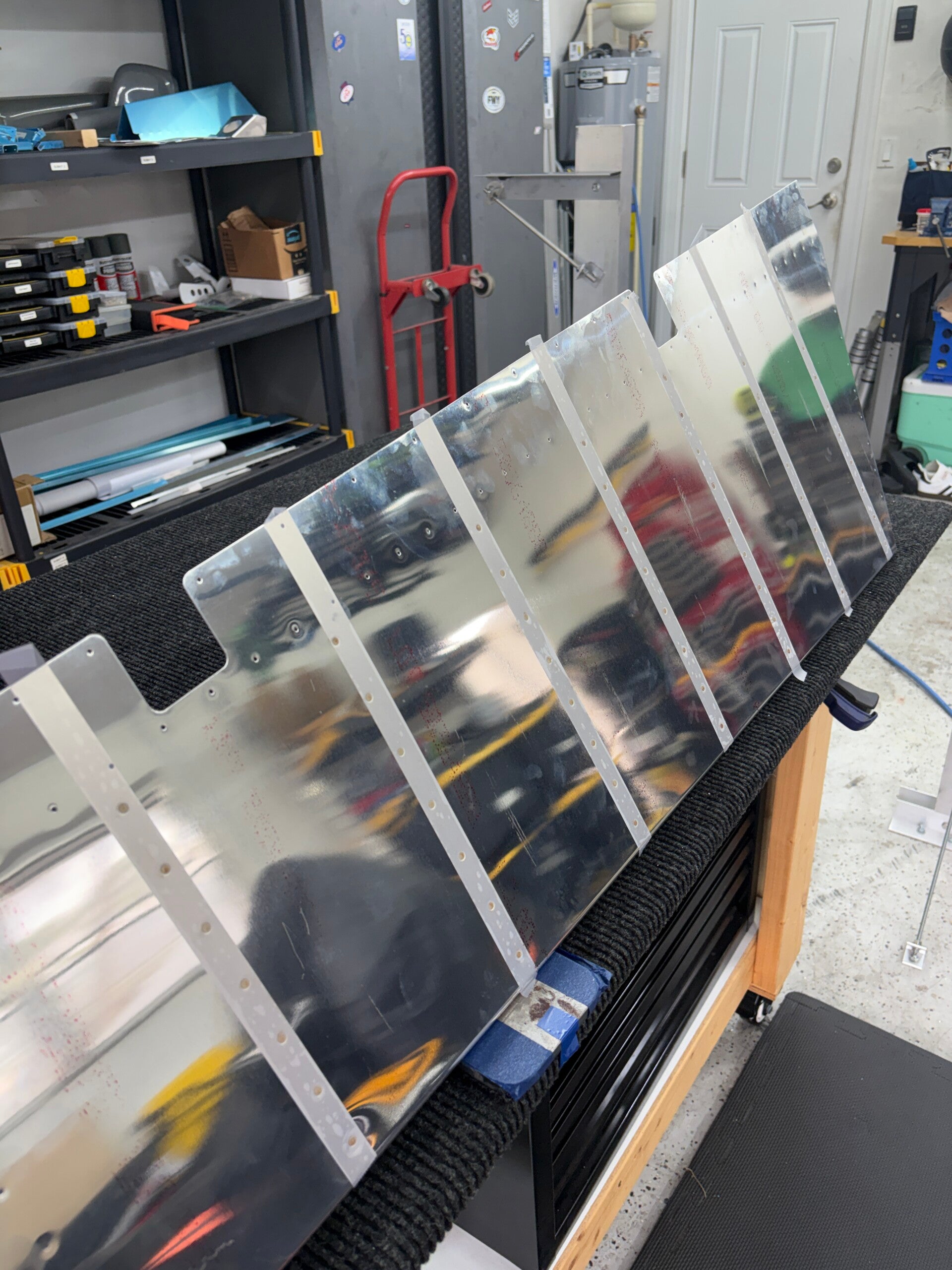
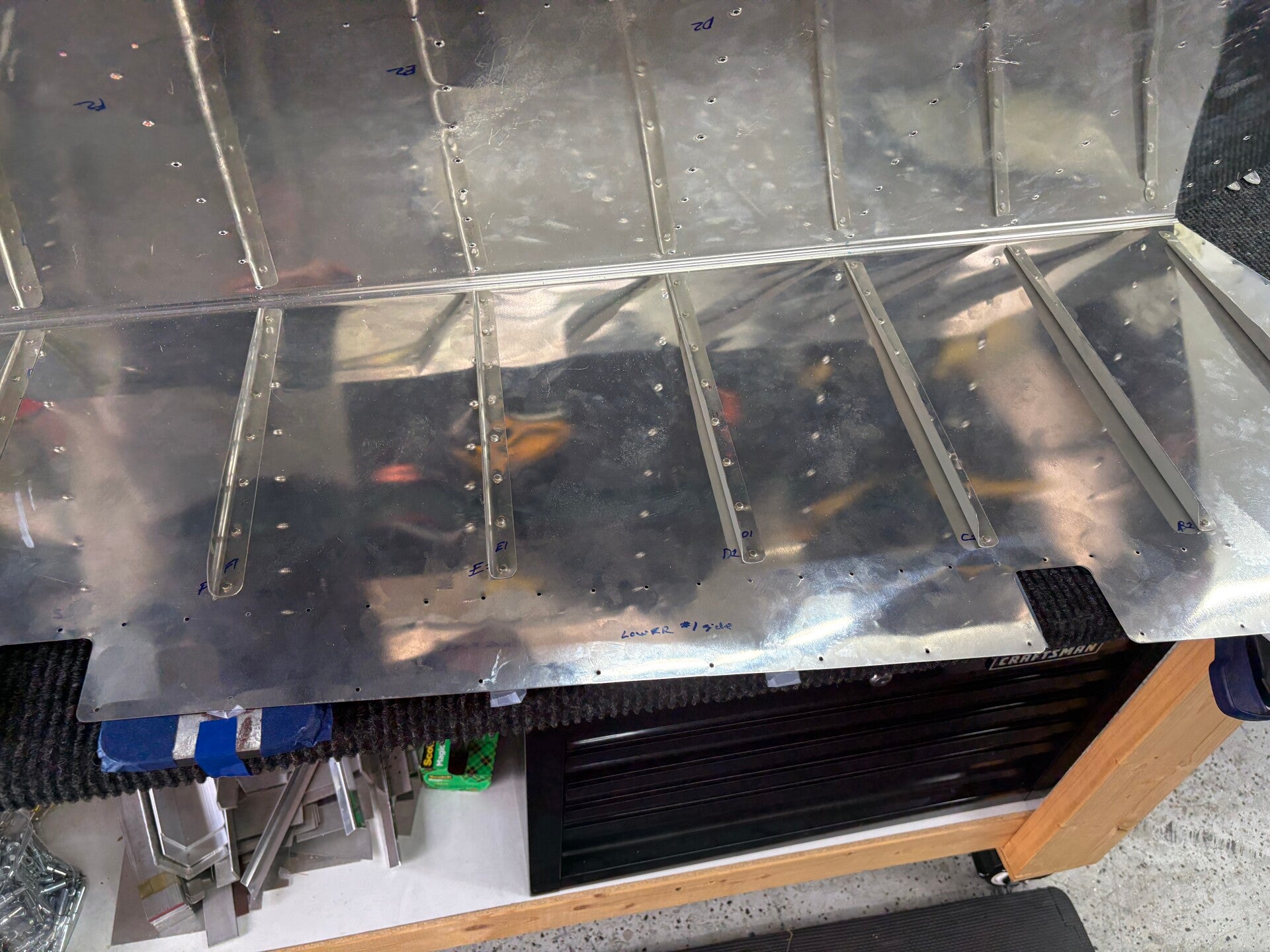
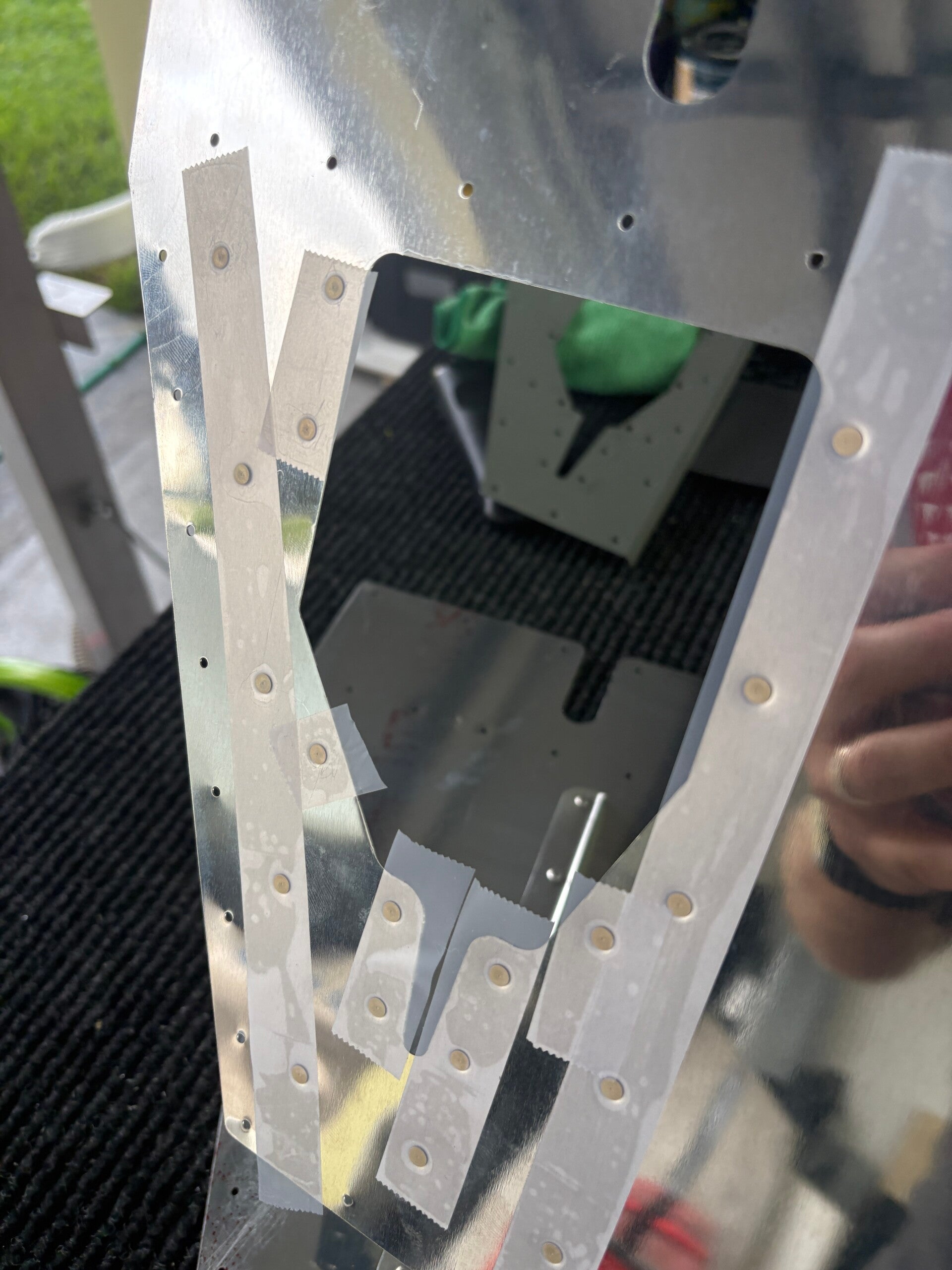
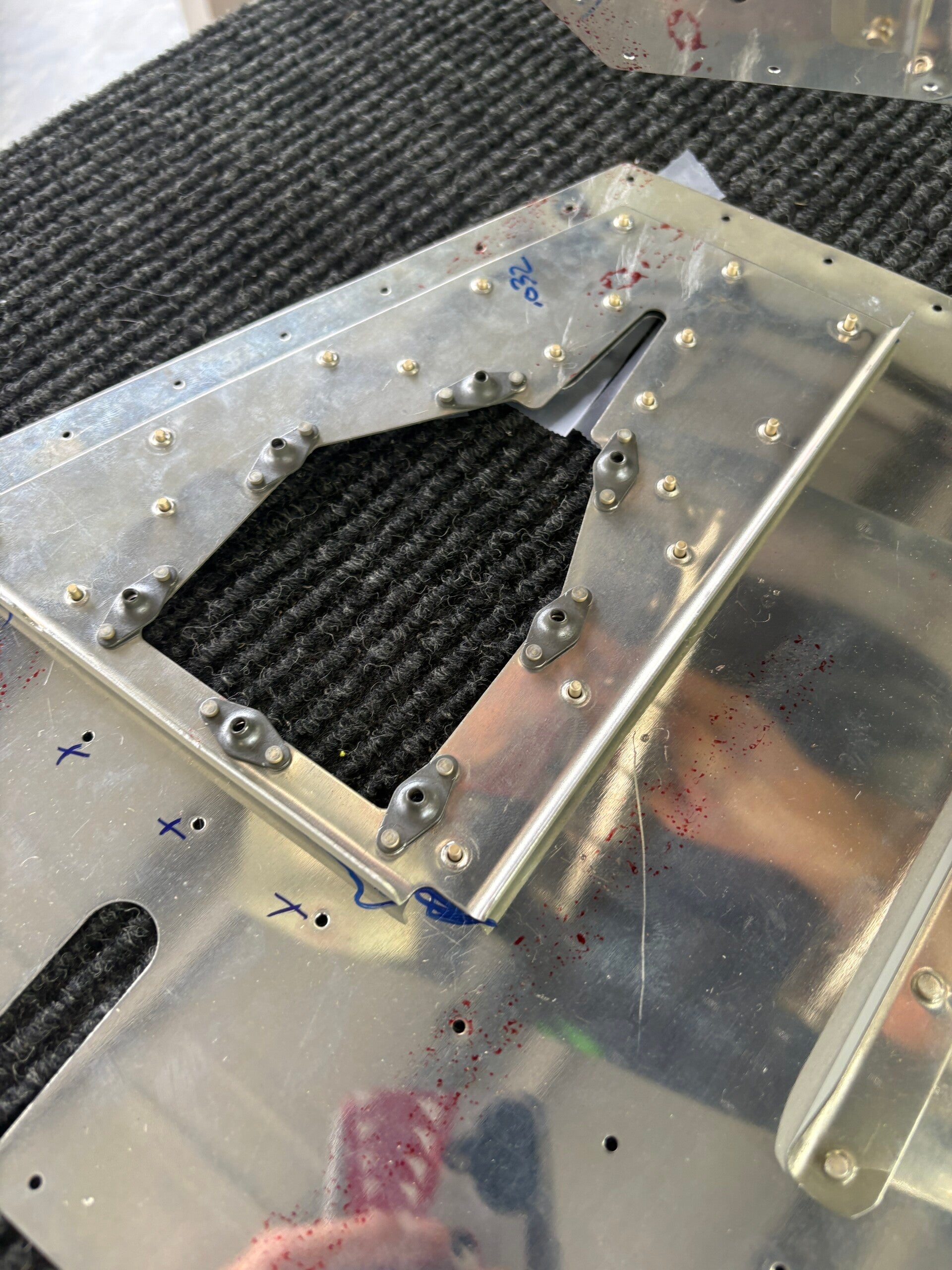
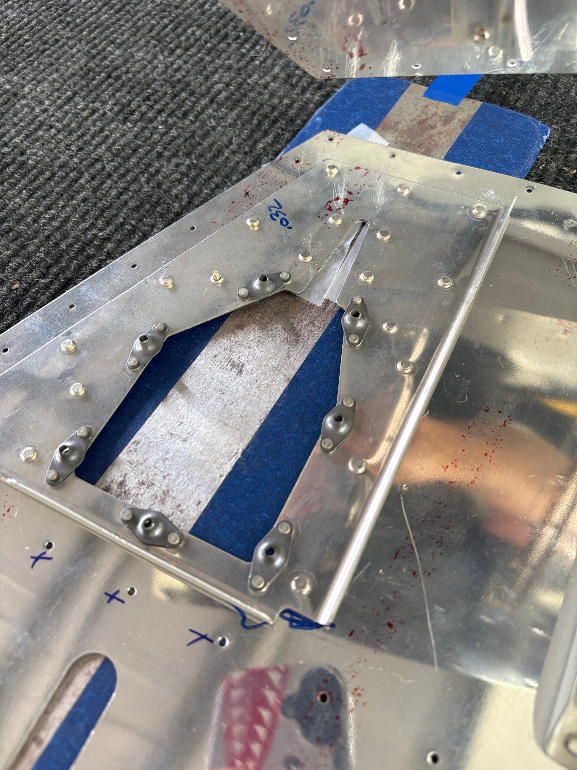
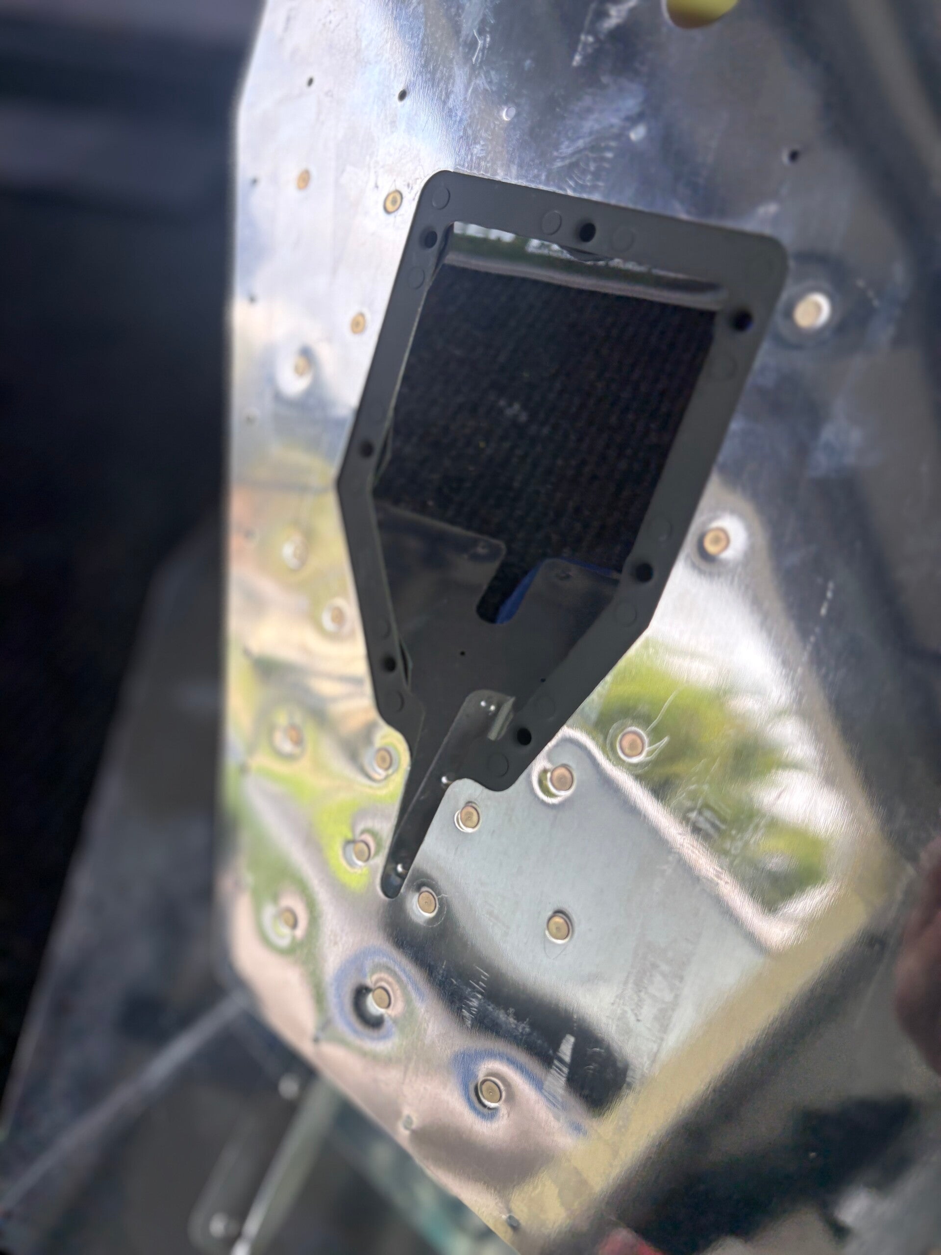
Building the Empennage
Discover the foundational steps of my RV-7A build, starting with the empennage kit. This section details the construction of the horizontal stabilizer, elevators, vertical stabilizer, and rudder, along with the essential fiberglass work.
The empennage is often the first kit builders receive from Van's, making it a critical starting point. This initial phase involves constructing the horizontal stabilizer, elevators, vertical stabilizer, and rudder. It's where many fundamental building skills, such as riveting, deburring, and fitting parts, are honed—skills that will be used throughout the rest of the aircraft project.
Empennage Total Project Hours: 80
Active section is the Elevators (horizontal stab completed on 7/20)
Horizontal Stabilizer - COMPLETE
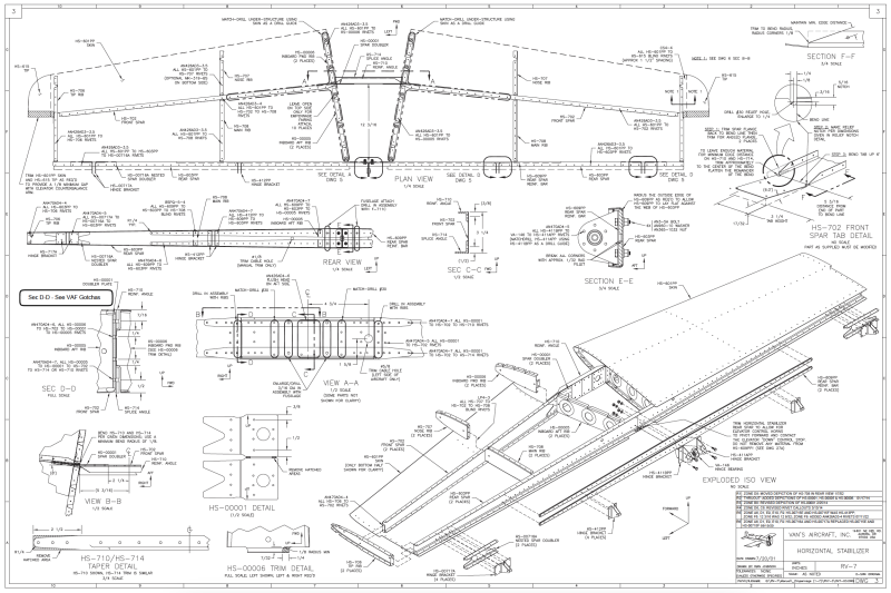
4/8/2026 (2 hours)
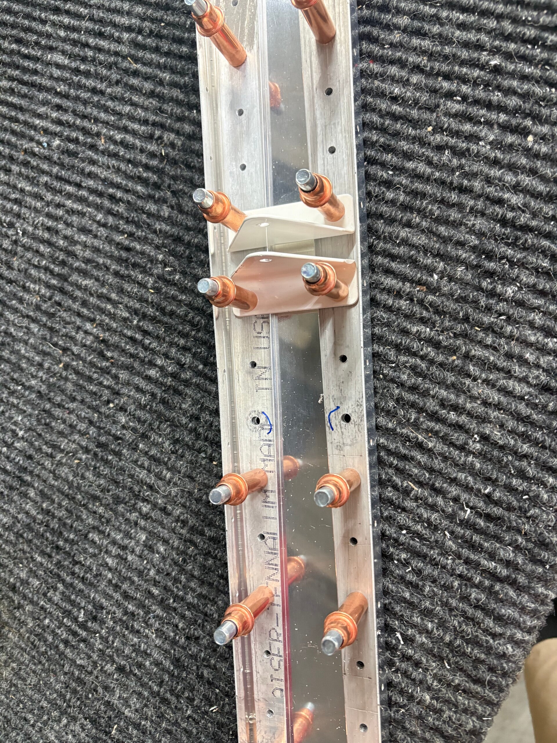
Rear spar
Steps 1-4
Rear spar cleco, drill, deburr
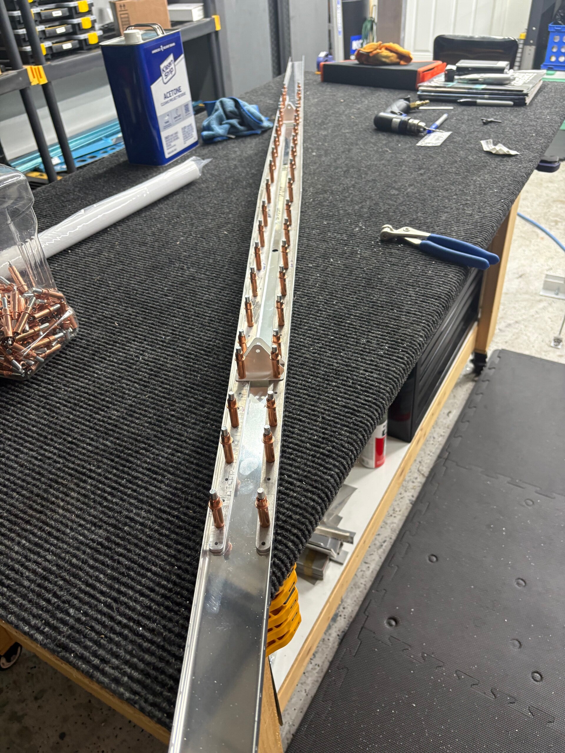
4/9/2026 (2 hours)
Rear Spar
Steps 5-12
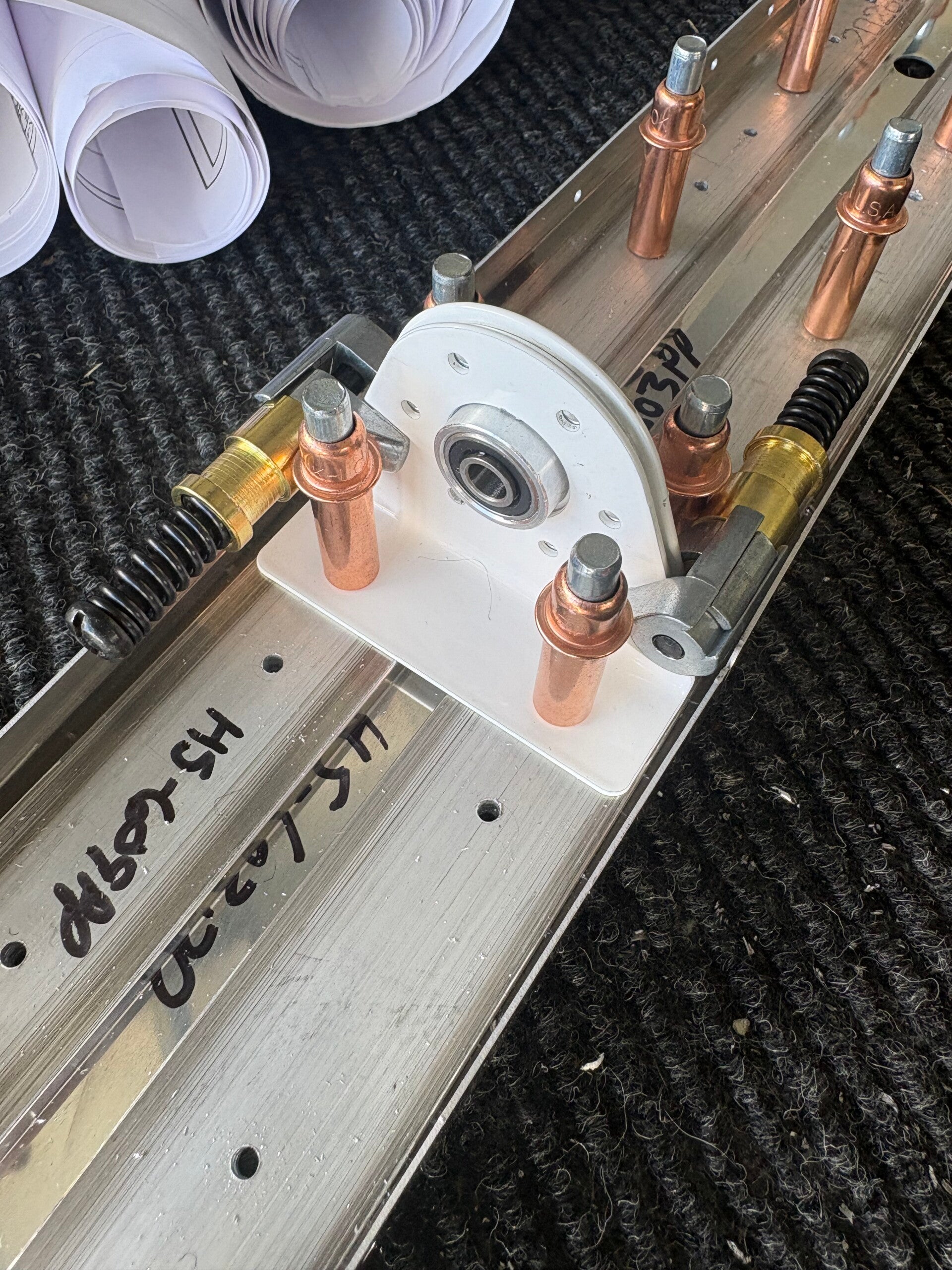
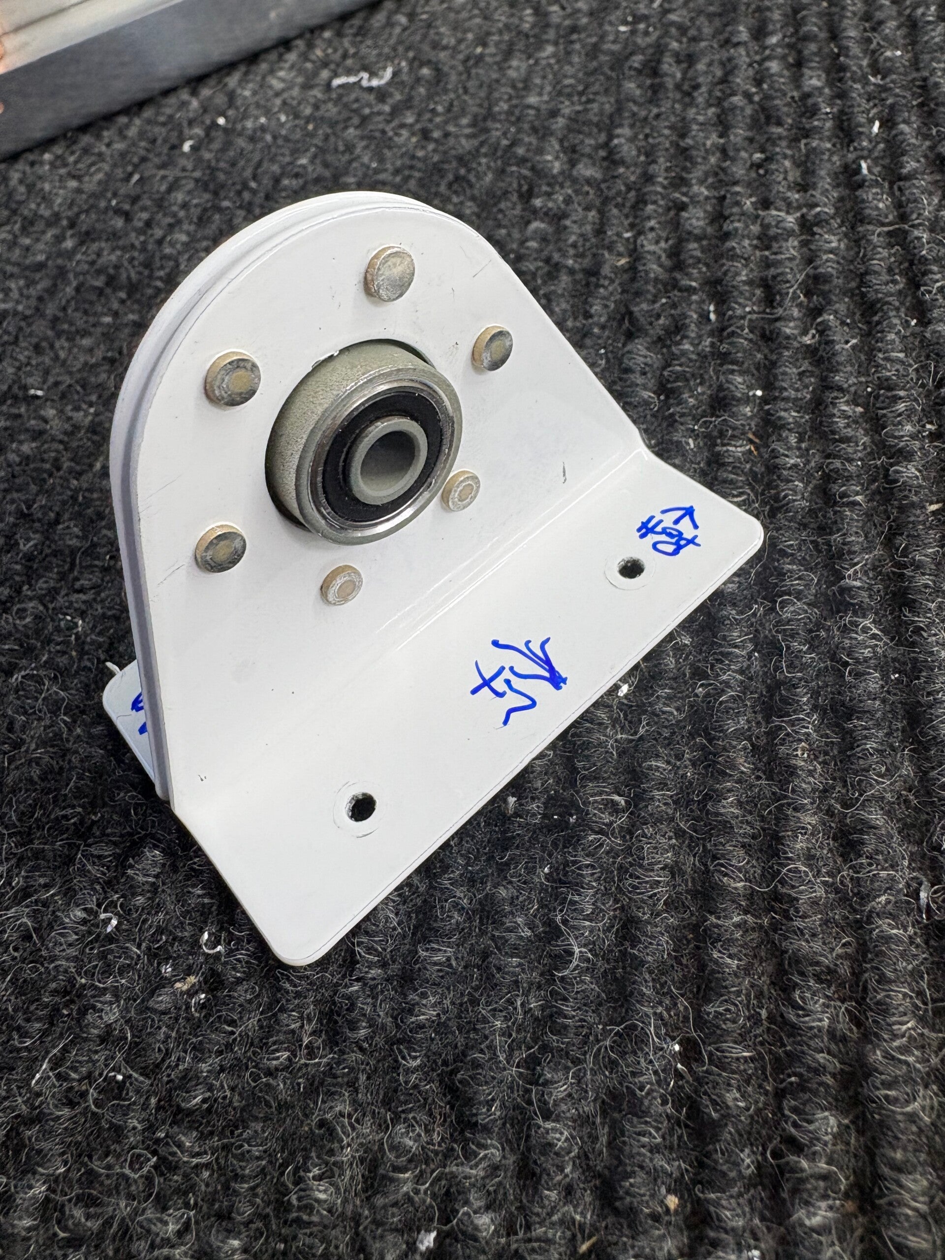
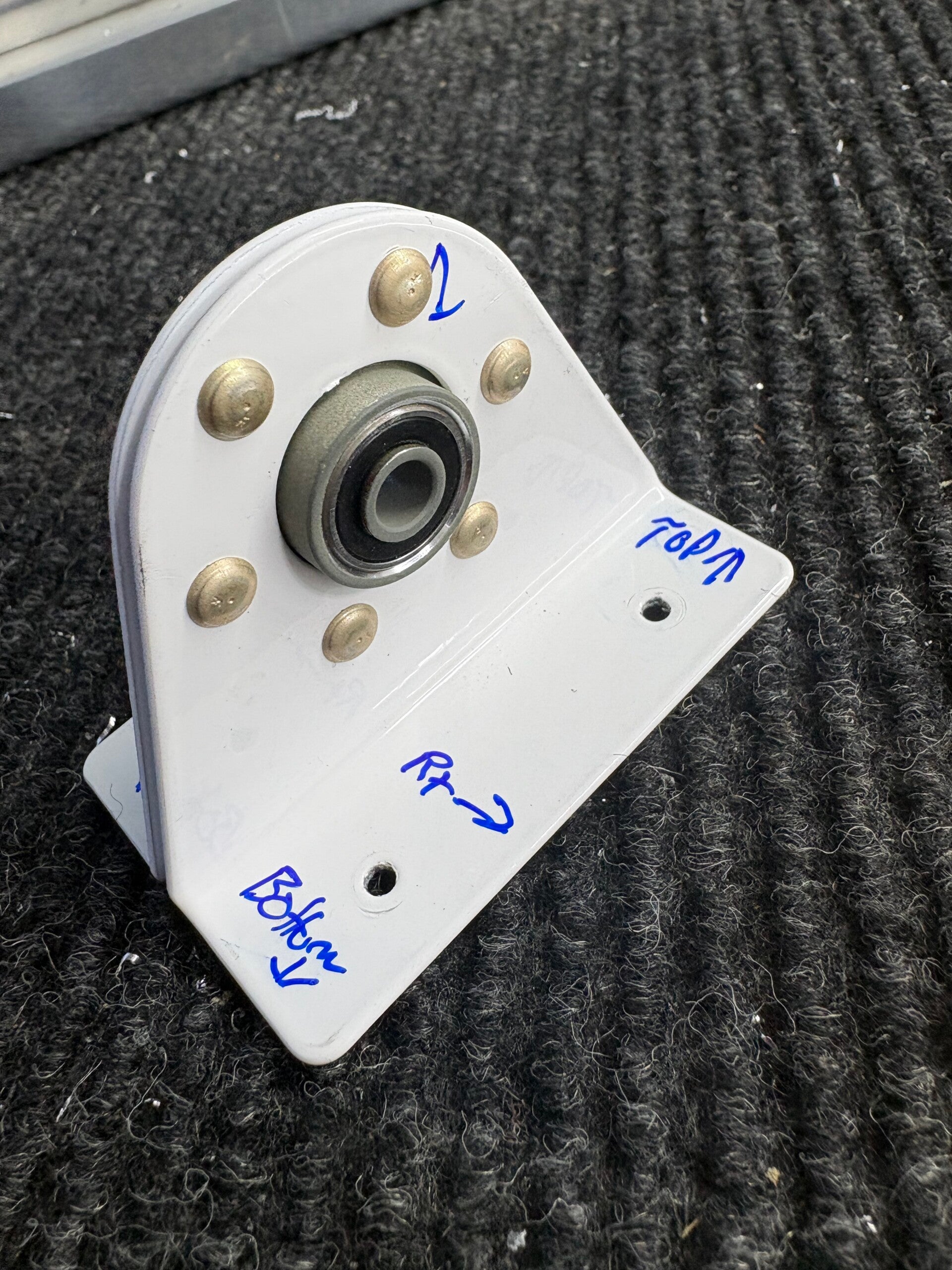
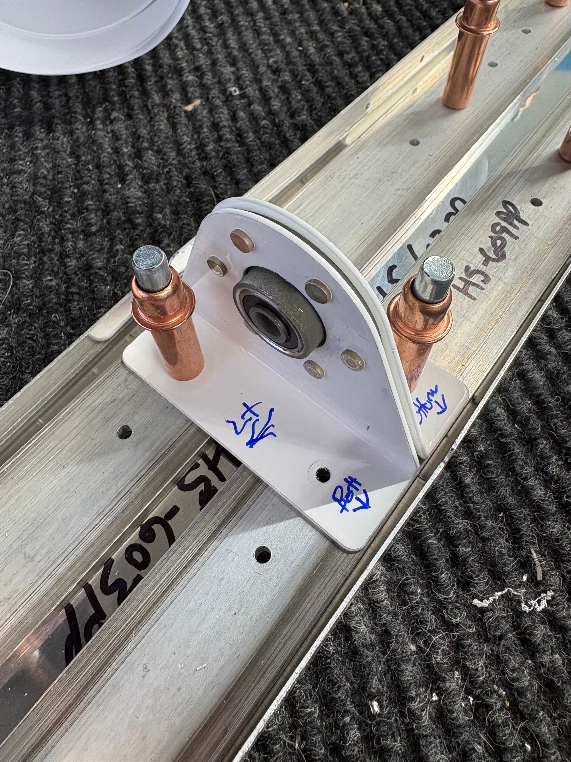
Hinge brackets - mount to rear spar, drill holes, deburr, then rivet. At this point in the manual, I need to start assembling the skeleton, however, the front spar and a rib are on backorder. Will pick this back up after parts are received.
7/20/2026 (1 hour)
Front Spar
Steps 1-4
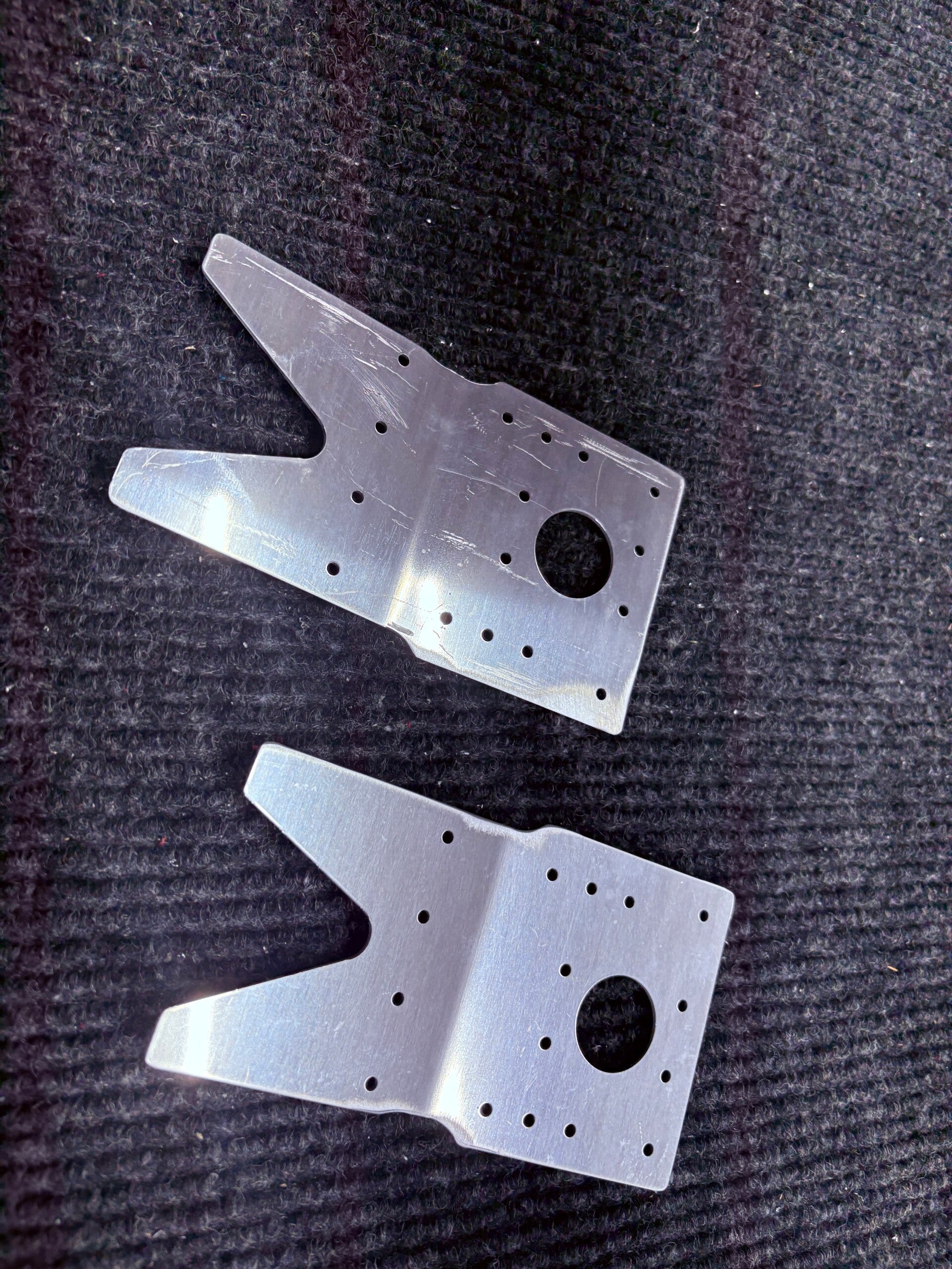
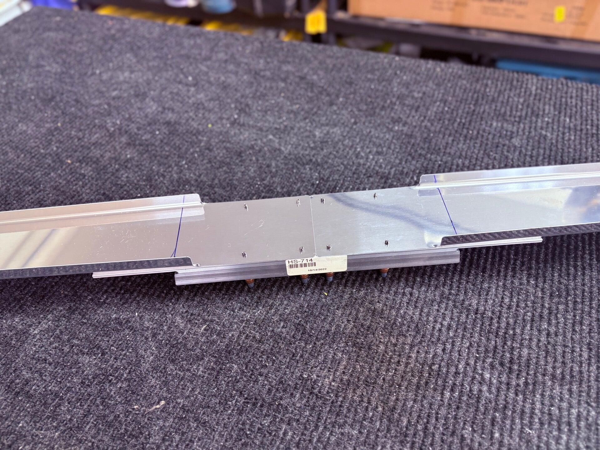
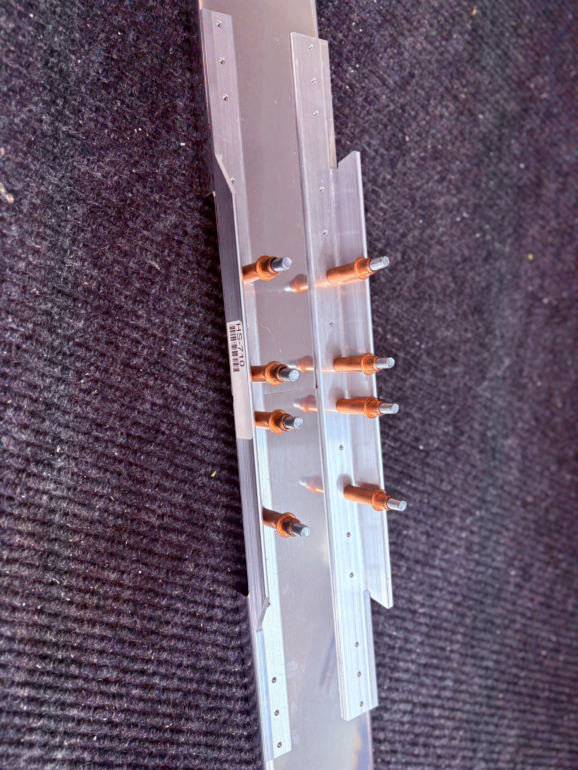
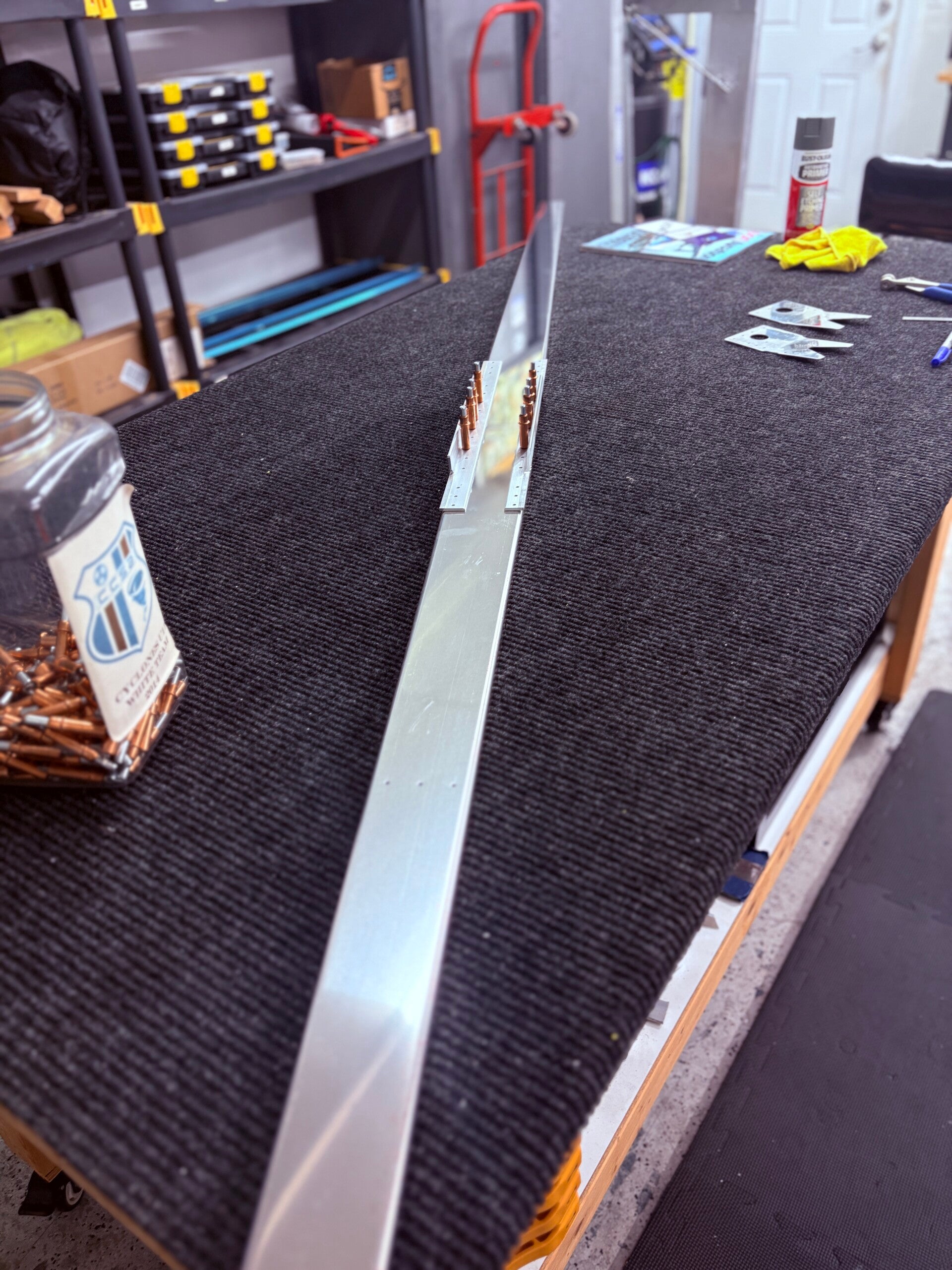
Nothing major here, just separated the two HS-00001 parts then cleaned up the edges. Next, clecoed the HS-710 and 714 reinforcement angles to the HS-702 spar. Measured and marked the bend line. The spars come straight, there needs to be a 6 degree bend in them, this will form the sweep back of the leading edge of the HS.
7/21/2026 (1 hour)
Front Spar
Steps 5
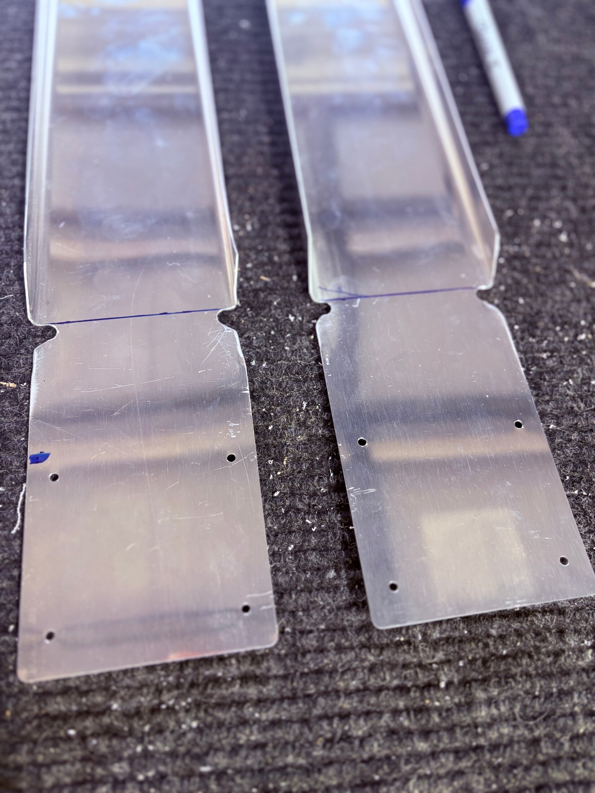
HS-702 - drilled the relief holes at the proper spots. Cut the rib web per plans. Cleaned up edges.
7/22/2026 (2 hour)
Front Spar
Steps 6-12
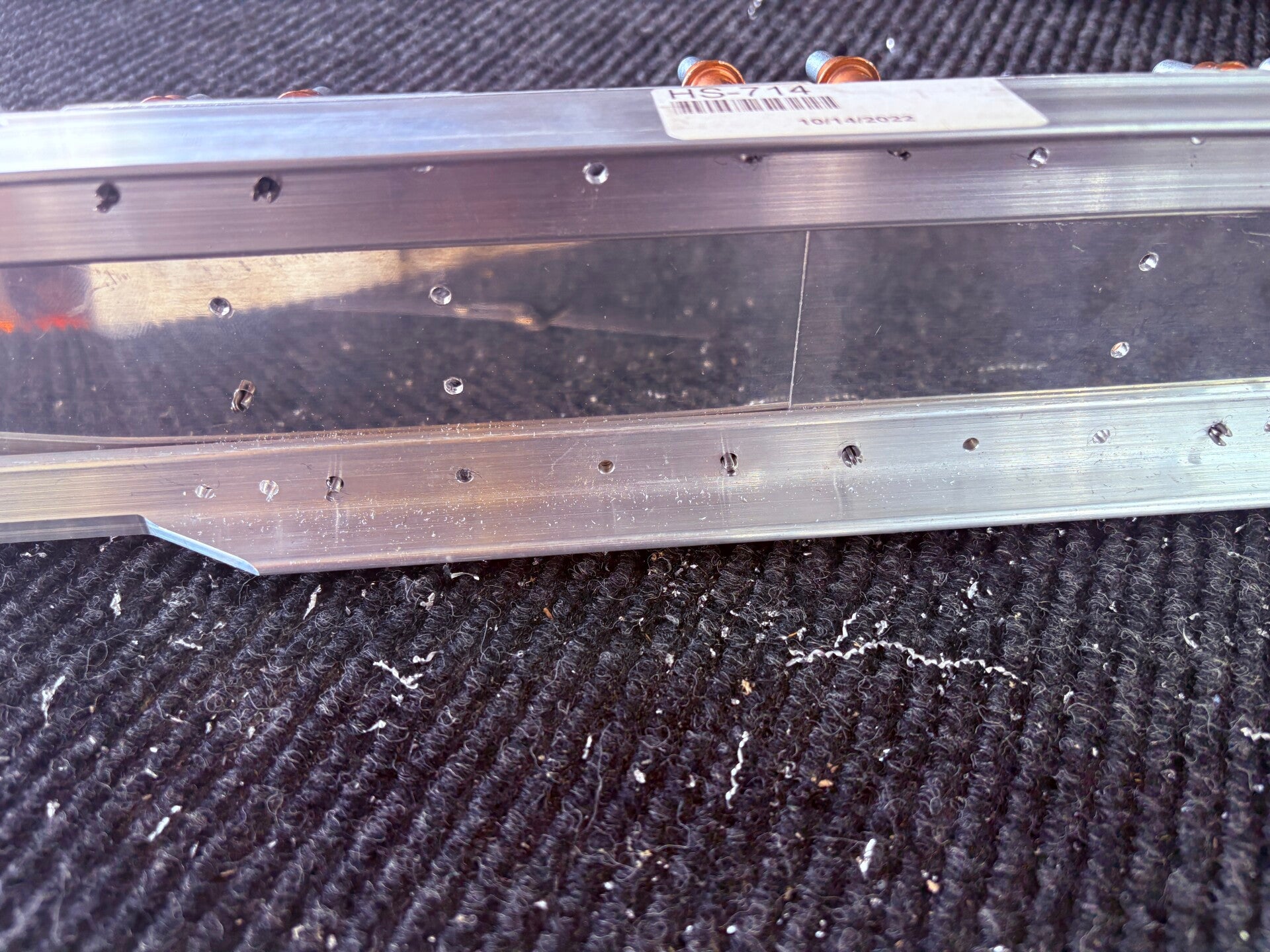
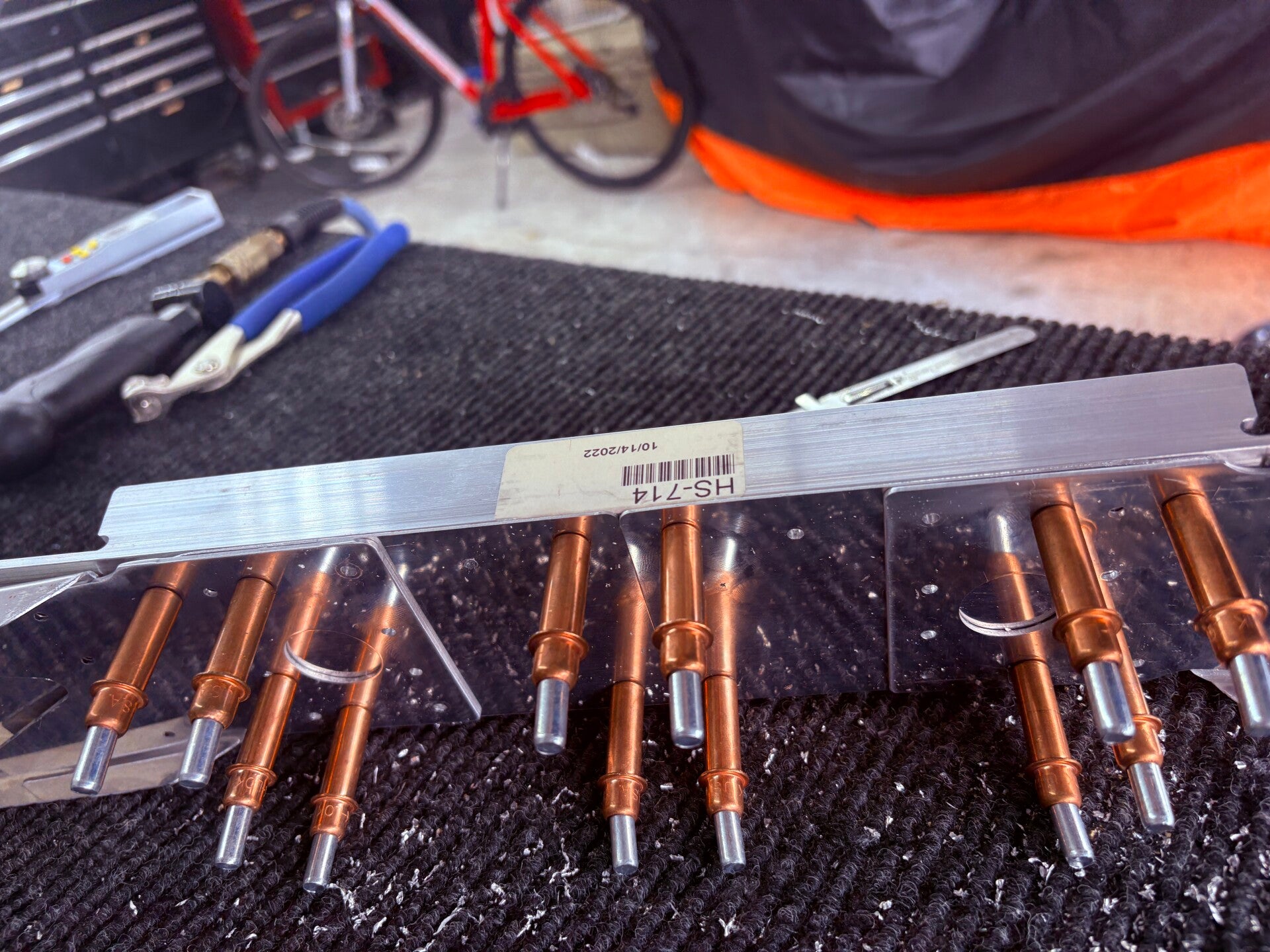
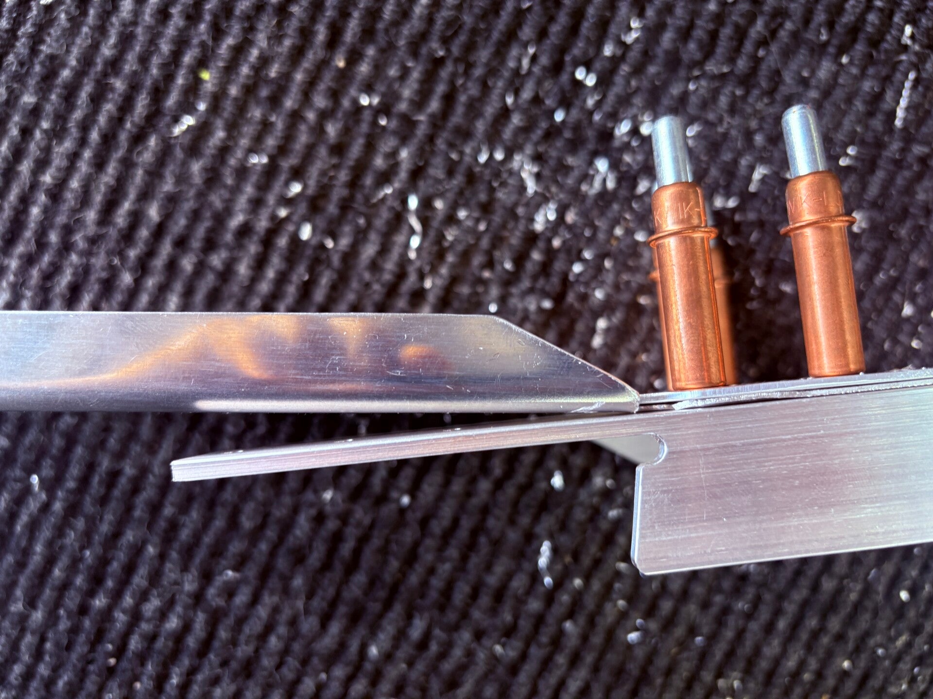
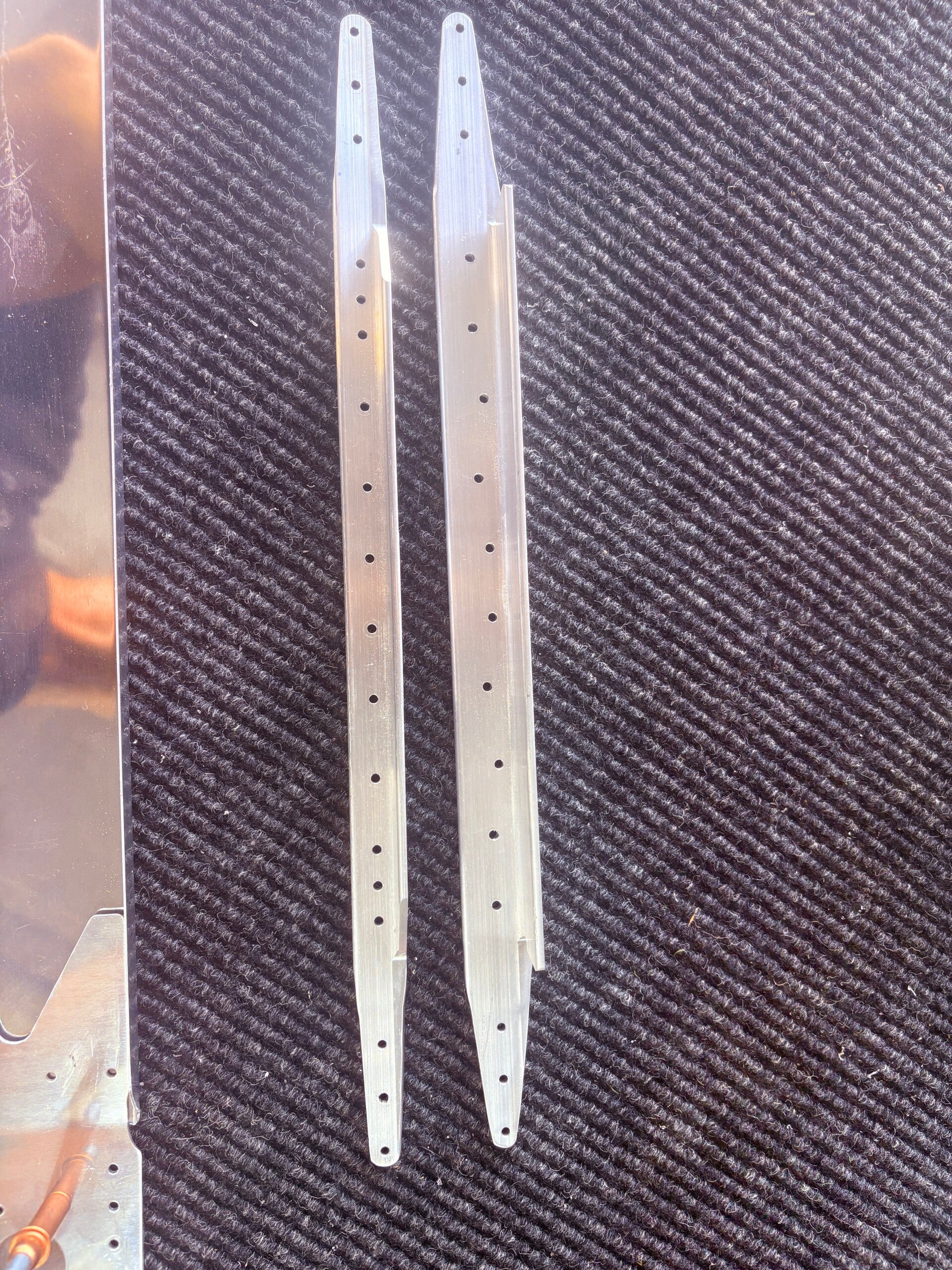
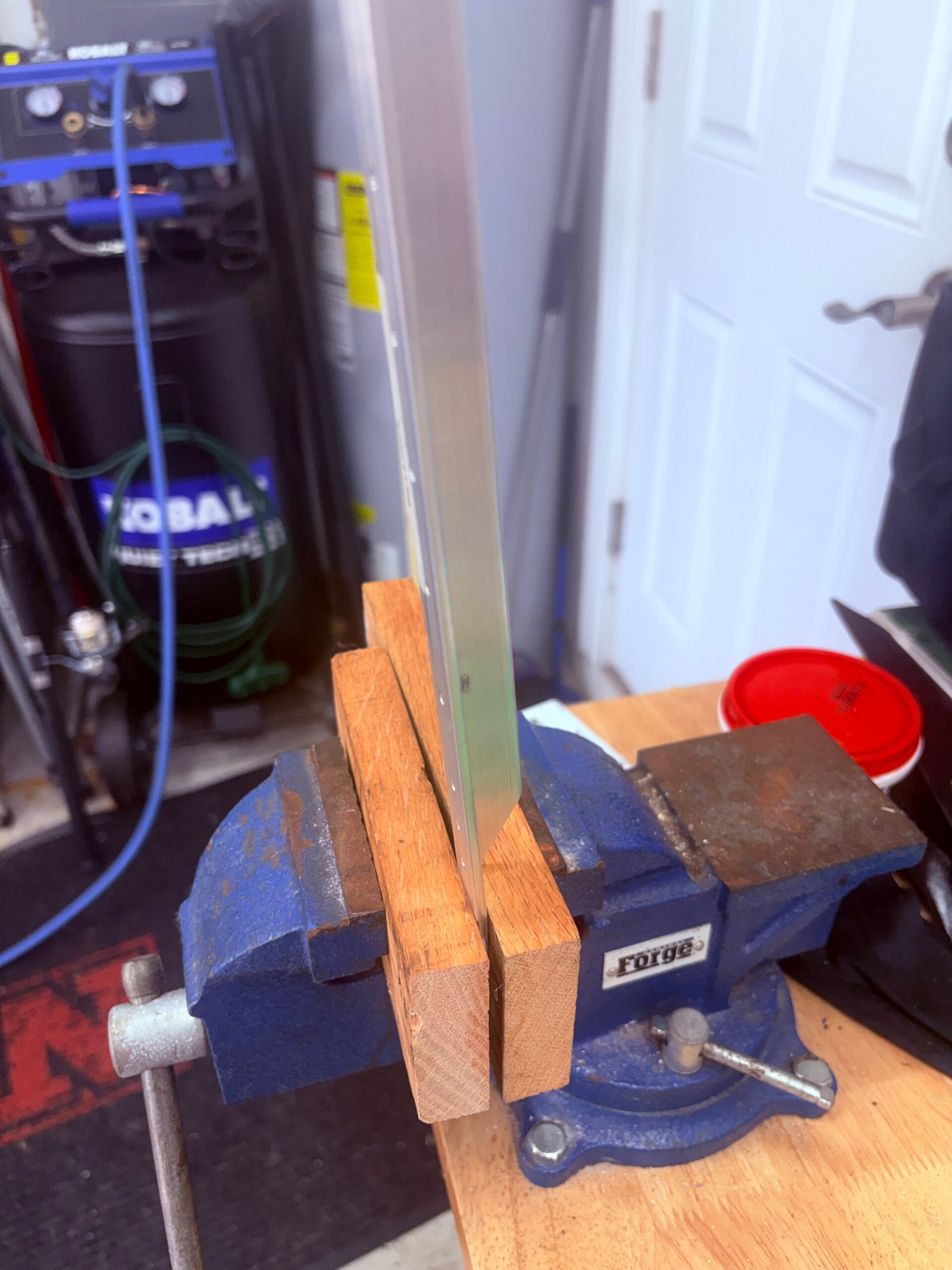
Trimmed the inboard ends of the HS-702 flanges. Bent the tab as shown in HS-702 Front Spar Tab Detail using blocks of wood. Clamped the HS-00001 spar doublers to the HS-702 spar channels. Match-Drilled #30 the inboard holes. Drill/match-drilled all the holes inboard of the HS-00006/HS-00005 rib attach points. Tapered the ends of HS-710 and HS-714. Bent the outboard ends of HS-710, HS-714. Dimpled HS-702 and countersink HS-710 and HS-714.
7/30/2026 (10 hours)
Another lengthy update spanning 2 weeks. Gunnar got in on the action. He and his friend Henry helped with skeleton cleco and other tasks.
PREPARING THE RIBS
Notch aft end of HS-00006 ribs around HS-714 and HS-710. Make one left and one right.
Flute, straighten, deburr, and edge-finish HS-00006, HS-00005, HS-706, HS-707, HS-708 as required.
DRILLING THE HORIZONTAL STABILIZER
Mark ribs for left/right.
On aft flange of HS-00006, mark holes per SEC D-D. Center-punch and pilot drill #40.
Draw a centerline on forward flange of HS-00005.
For the left side, cleco HS-702, HS-603PP, HS-706, HS-707, HS-708 together.
Drill HS-706, HS-707, HS-708 rib-to-spar holes #30, except HS-708/HS-603PP holes.
Un-cleco, deburr, clean chips, and re-cleco.
Cleco HS-601PP skin.
Enlarge HS-708/HS-603PP holes to #21.
Cleco HS-00001, HS-710, HS-714 to HS-702.
Install HS-00006 and HS-00005. Mark rib flange hole locations using skin holes as guides.
Remove ribs and flute as needed between rivet holes.
Reinstall HS-00006/HS-00005 and clamp HS-00006 to HS-601PP and spar assembly.
Match-drill #30 HS-00005 aft flange to HS-603PP. Remove and clean.
Match-drill #40 HS-00006 aft flange to HS-702 and HS-00001.
Mark and drill #40 the two holes common to HS-00001, HS-702, HS-710/HS-714, aligned with HS-00006 holes. See SEC D-D.
Reinstall HS-00005, align centerline, clamp tightly against HS-00001, cleco aft flange to rear spar, and clamp top/bottom flanges to HS-601PP.
Match-drill forward flange of HS-00005.
Cleco HS-00716A doublers to rear spar.
Cleco ribs and spar assembly together.
Starting at rear spar and working forward, match-drill HS-601PP skin to HS-00005.
Ensure front flanges of HS-00005, HS-702, HS-710, HS-714, HS-00001 and aft flange of HS-00006 are tight. Re-clamp HS-00006.
Drill remaining HS-601PP skin holes to final size. Start at HS-708 center rib/rear spar and work along rib and toward tip. Cleco every 2nd–3rd hole.
Remove skin and drill remaining holes in HS-714, HS-710, HS-00001. Remove these parts.
Repeat all drilling steps for the right side.
PREPARING HORIZONTAL STABILIZER PARTS
Mark and disassemble all parts.
Deburr all skin and skeleton holes.
Dimple understructure with pneumatic/hand squeezer.
Dimple skin rivet holes with C-frame.
Smooth/finish all edges.
Prime as required.
HS-609PP, HS-710, HS-714 are not Alclad and must be primed before riveting.
RIVETING THE HORIZONTAL STABILIZER
Locate rear spar holes for HS-706, HS-708, HS-00005 and HS-412PP hinge brackets. Tape them off to prevent accidental riveting.
Rivet HS-609PP bars to HS-603PP spar channels per plans.
Rivet HS-412PP hinge brackets to rear spar.
Rivet HS-00717A hinge brackets and HS-00716A doubler to rear spar.
Bolt HS-411PP center bearing to spar using torque chart.
Rivet HS-710, HS-714, HS-00001 to HS-702 front spars. Pay attention to flush center rivets.
Rivet HS-00006 and HS-00005 to front spar assembly.
Place left-side HS-601PP skin on clean padded surface.
Cleco and rivet HS-707 to top side of skin.
Cleco HS-706. Temporarily cleco HS-708 and aft flange of HS-707 to hold skin tight, then rivet bottom of HS-707 to HS-601PP. Remove HS-708.
Cleco forward spar assembly to HS-706, HS-707, HS-601PP, then cleco HS-708.
Blind rivet HS-702 to HS-707 and HS-708.
Rivet HS-702 to HS-706.
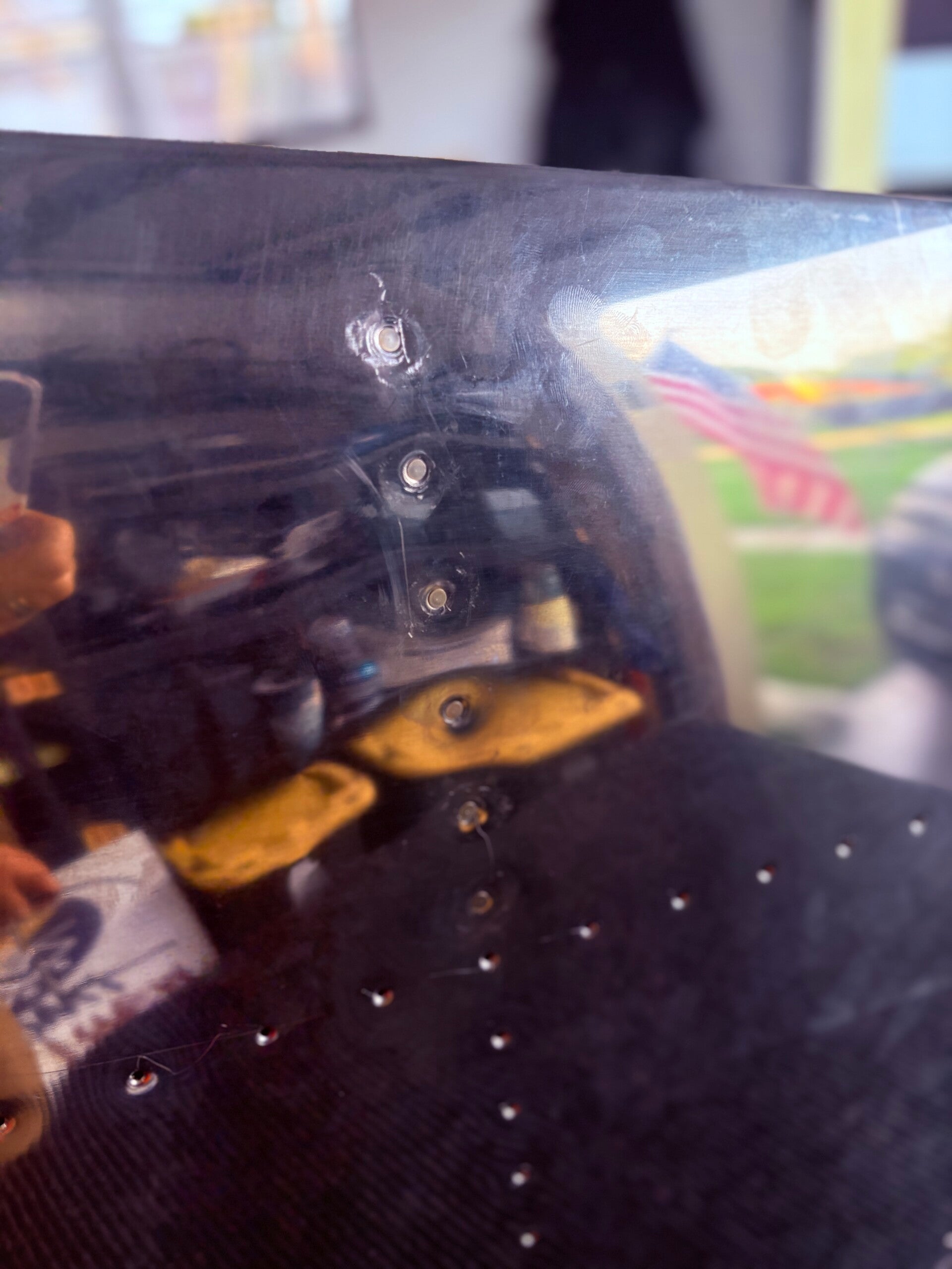
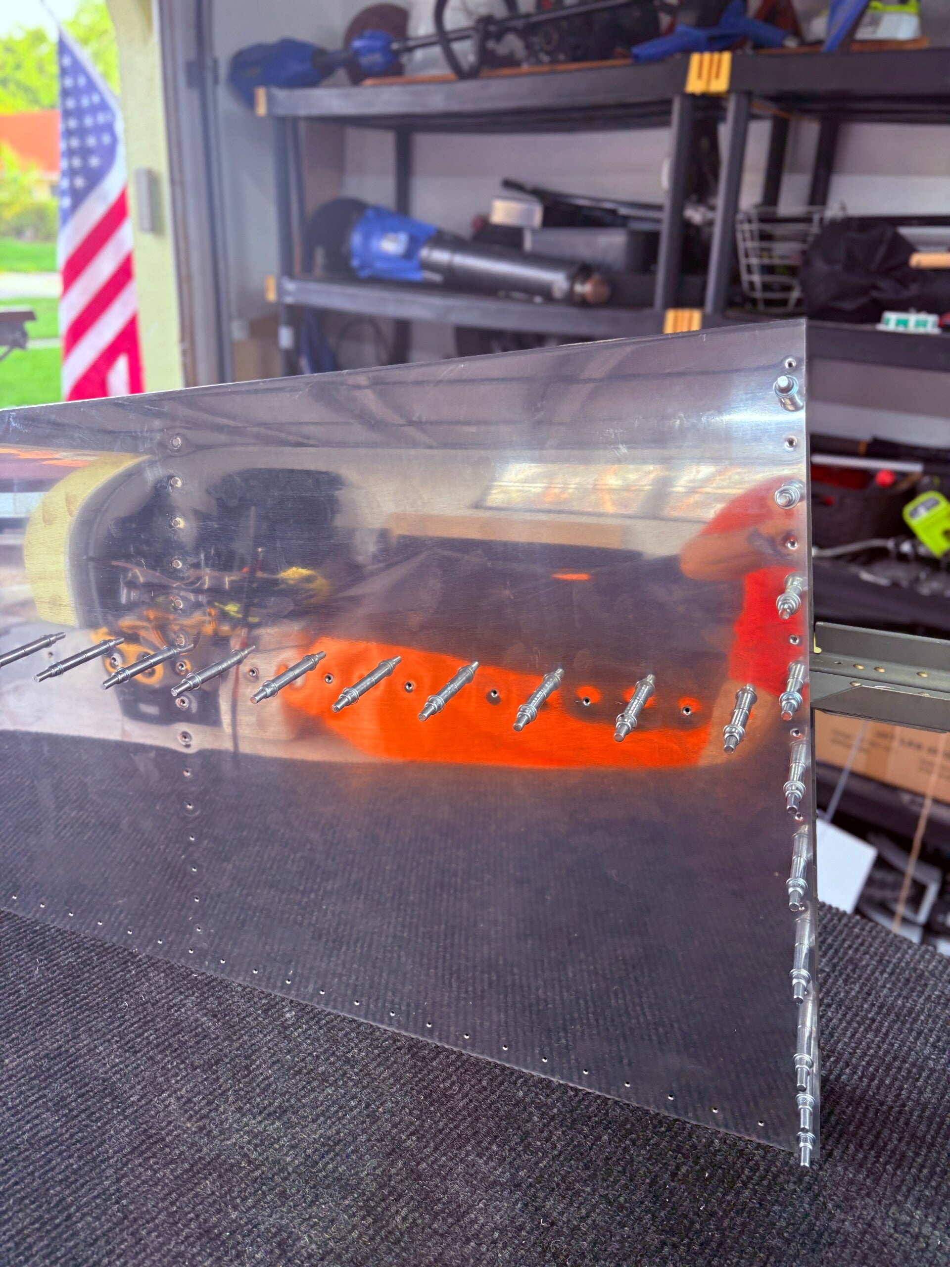
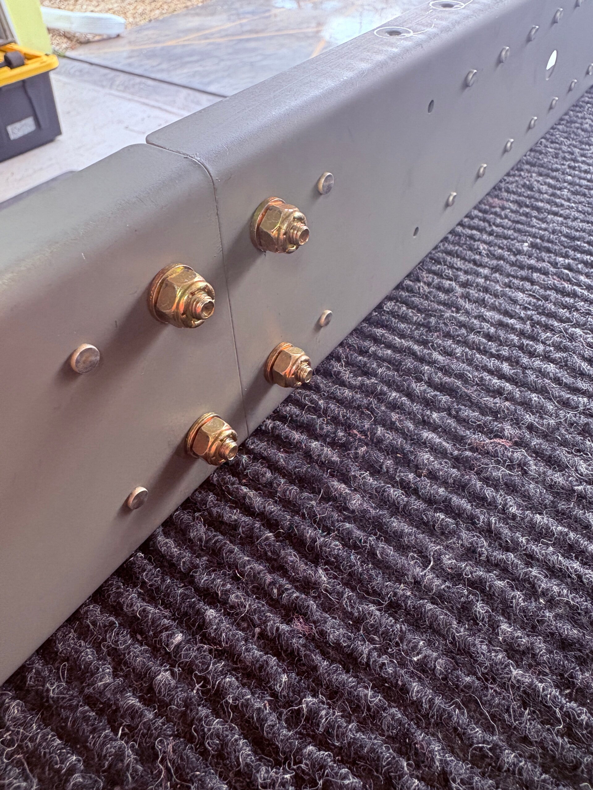
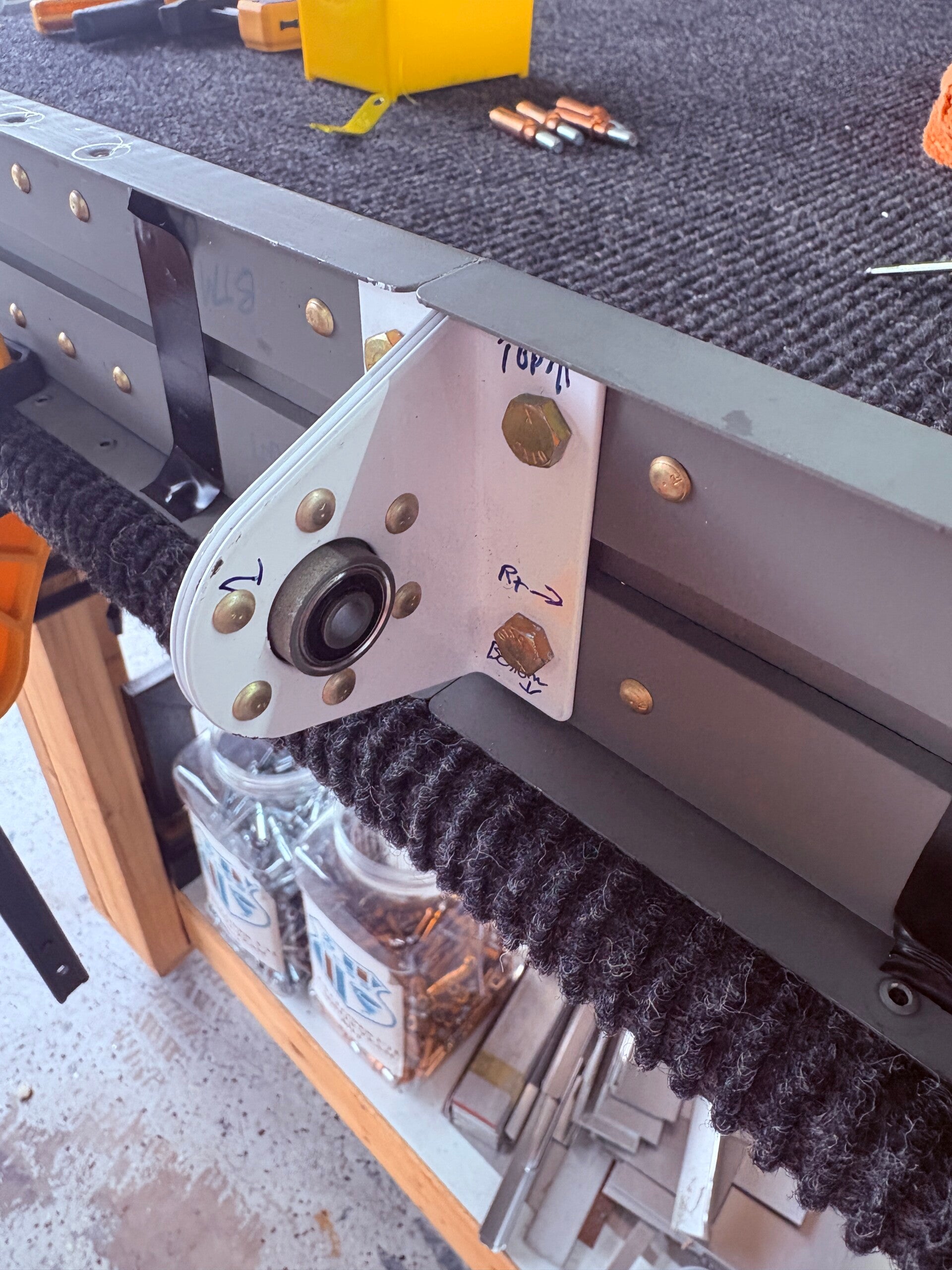
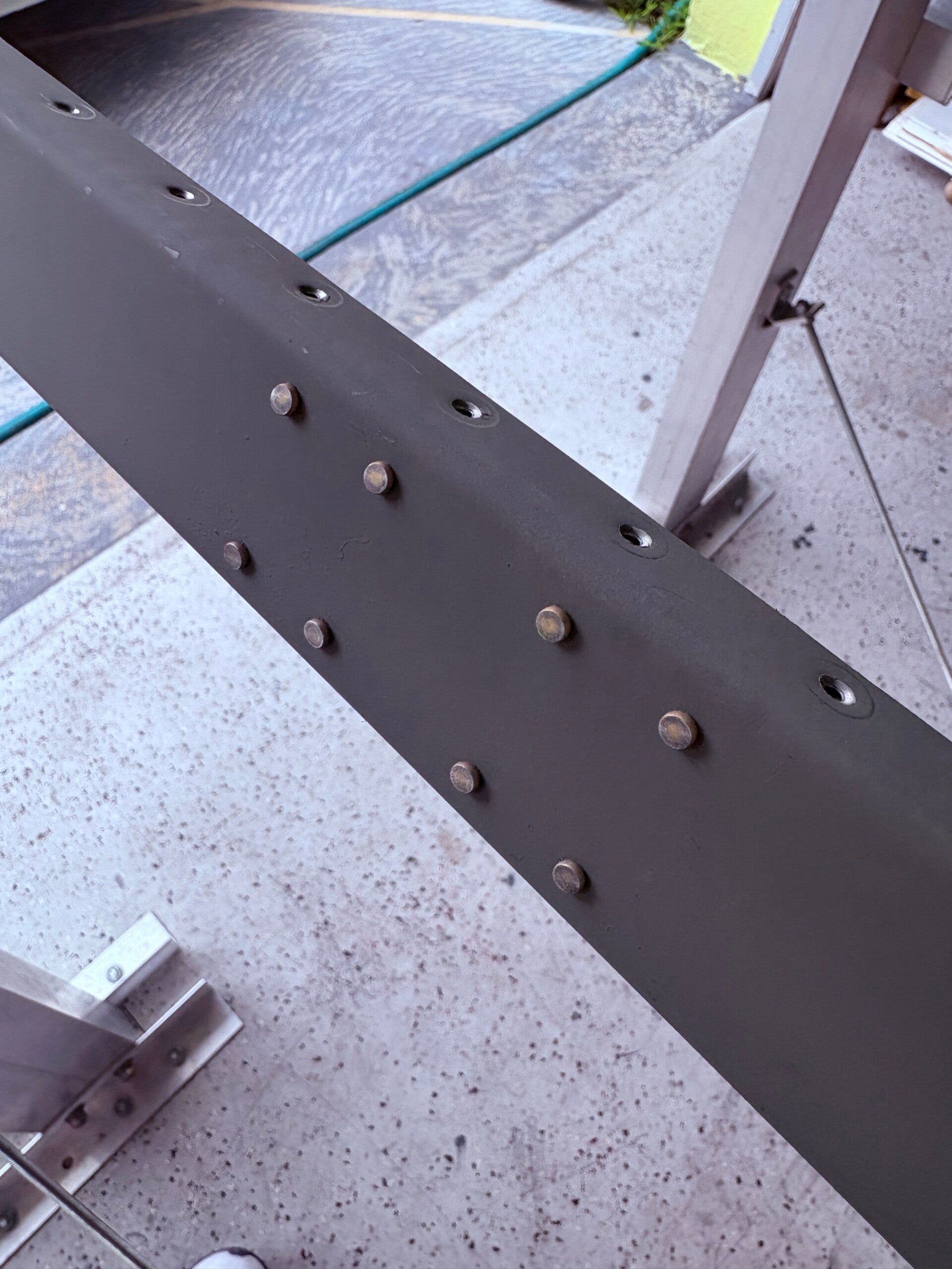
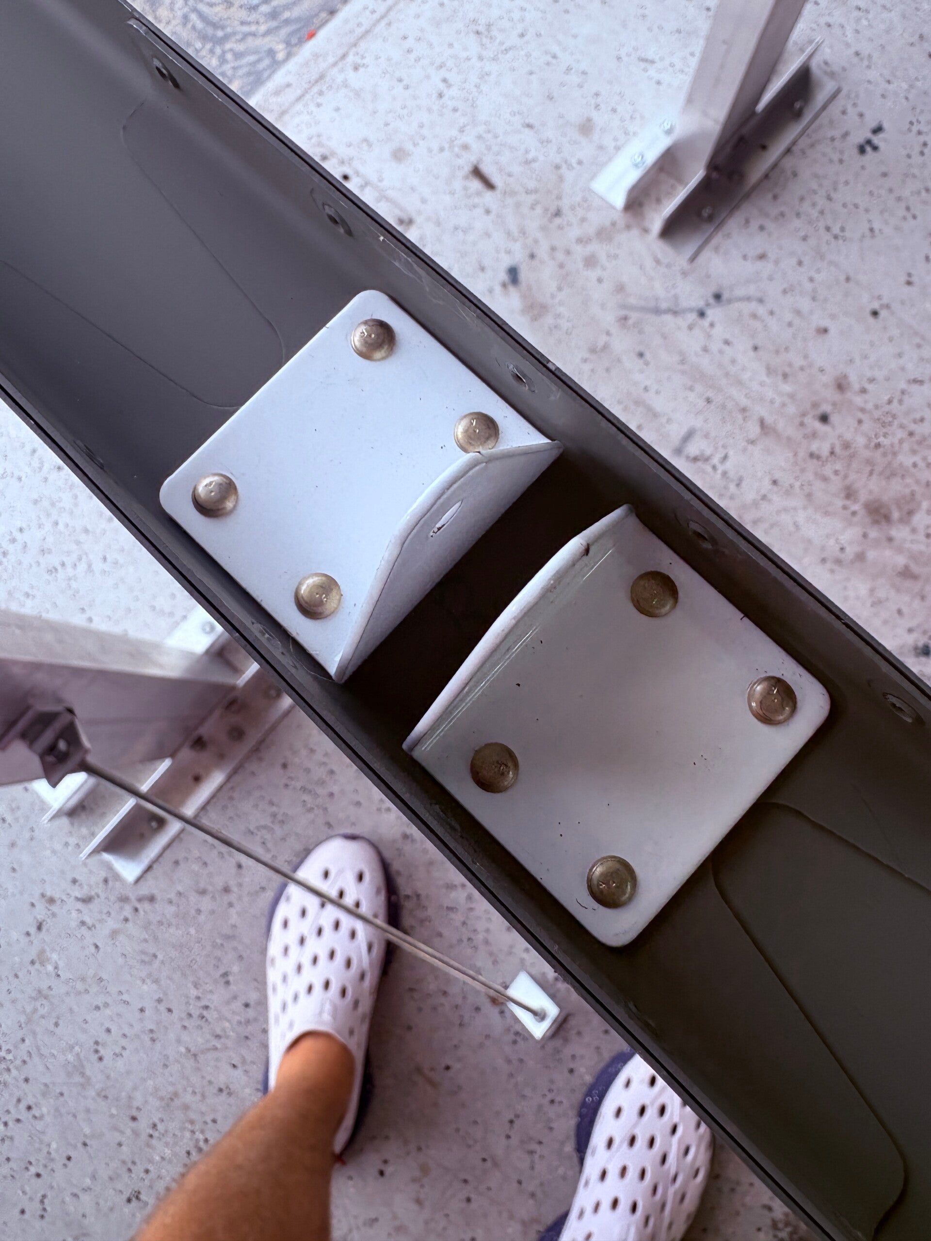
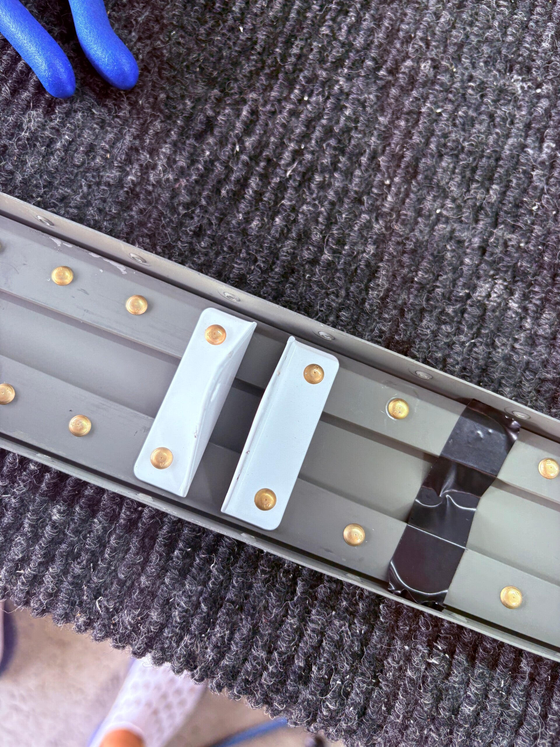
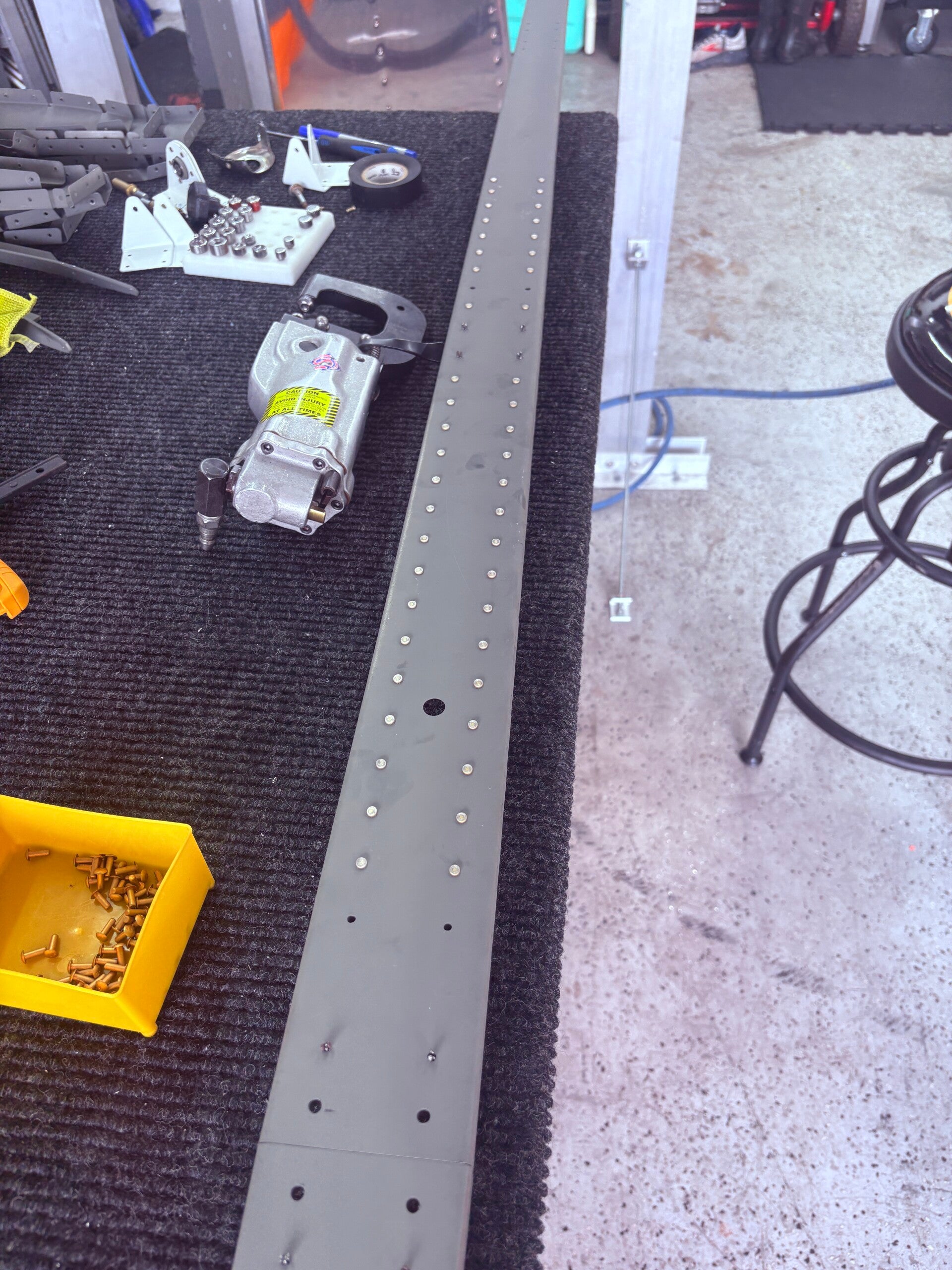
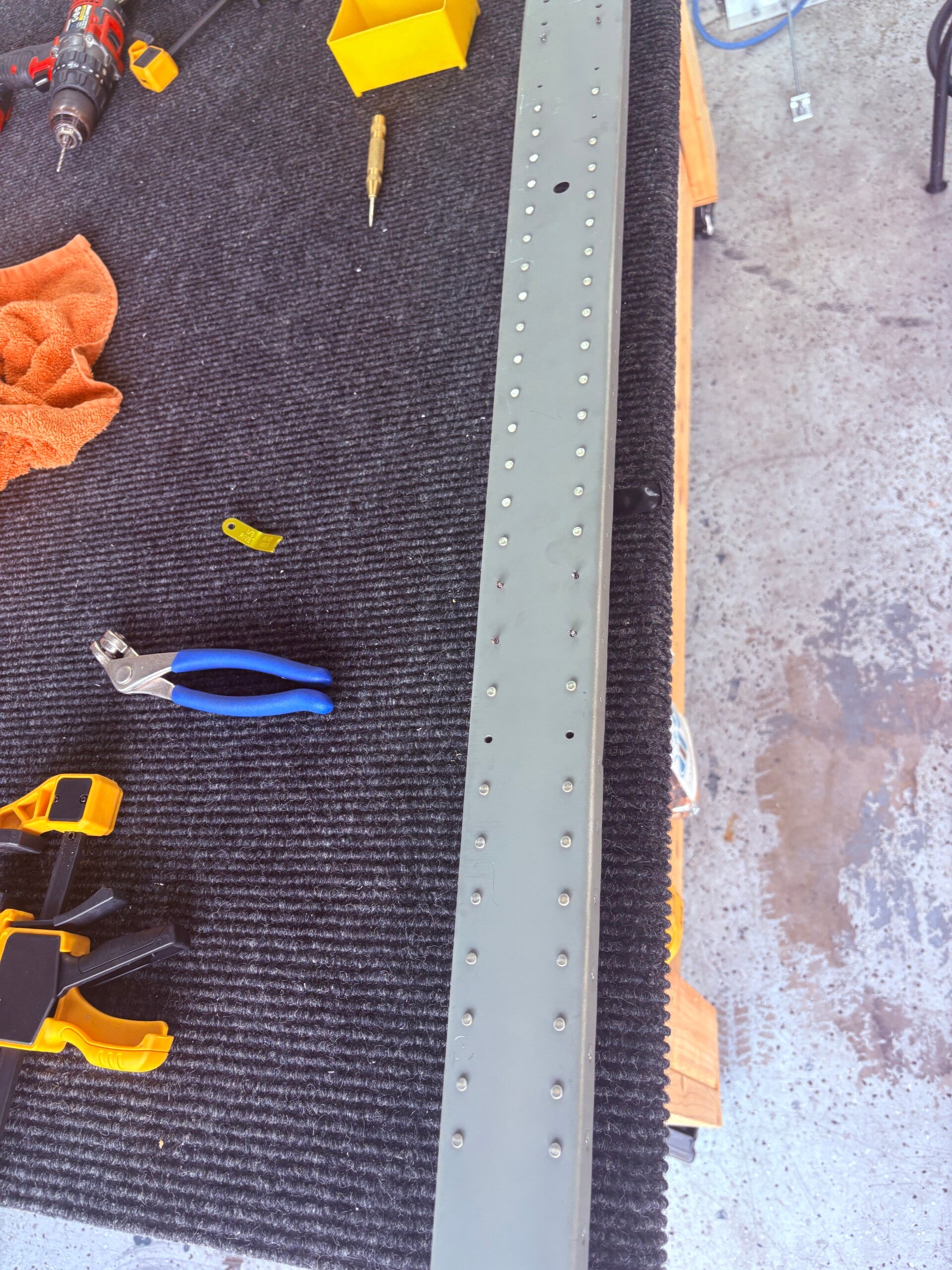
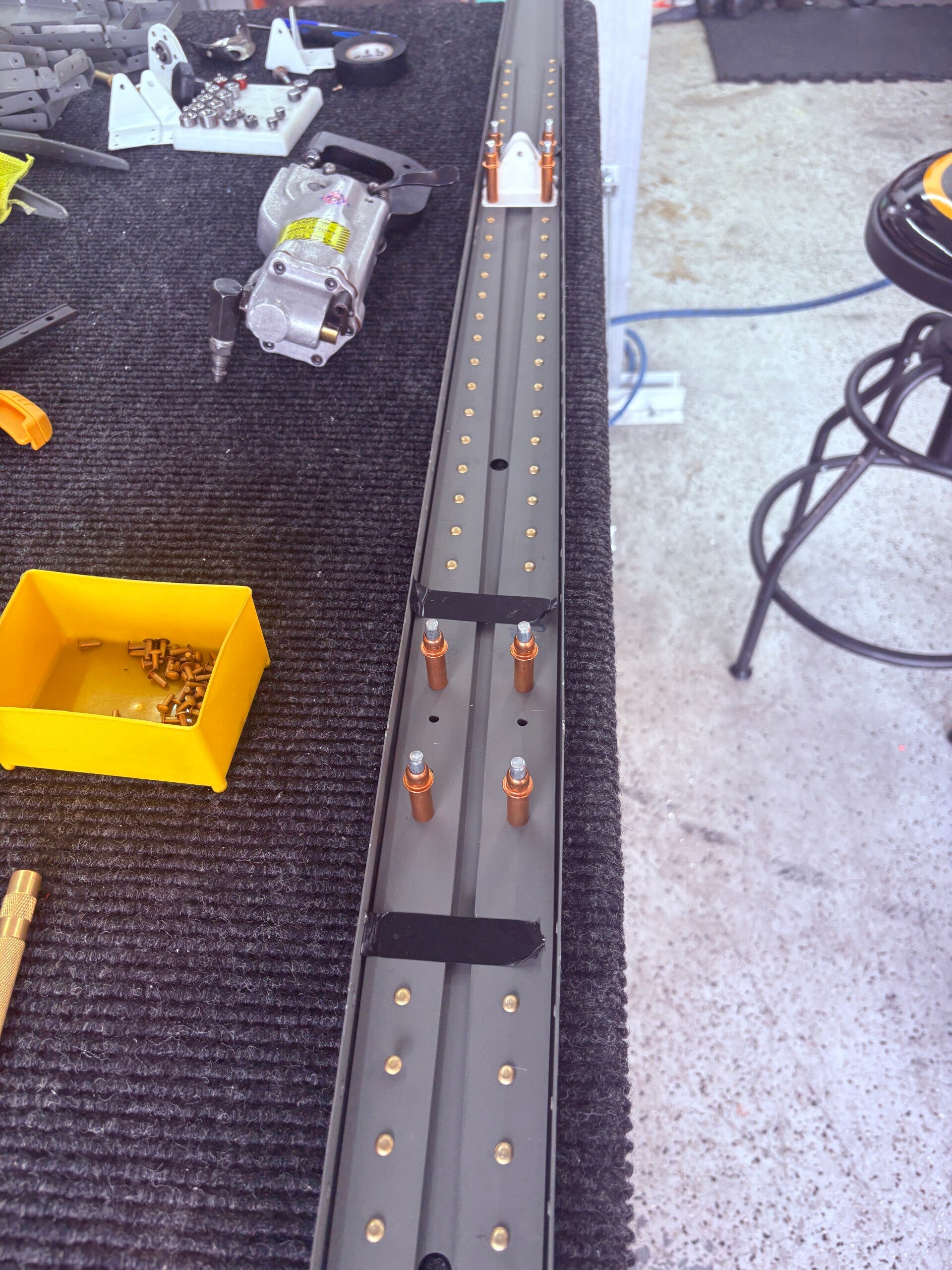
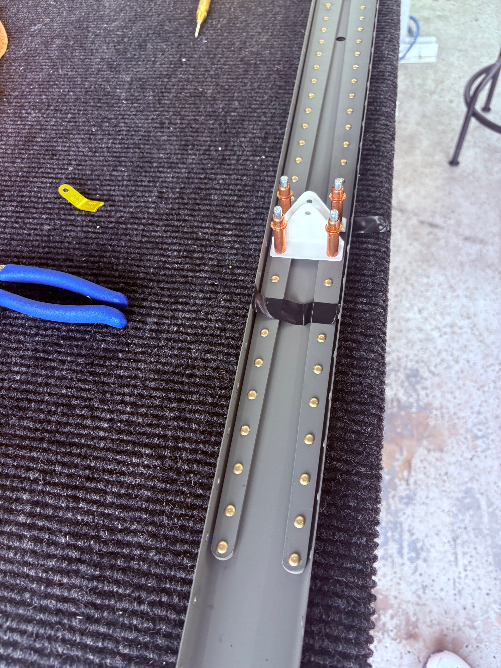
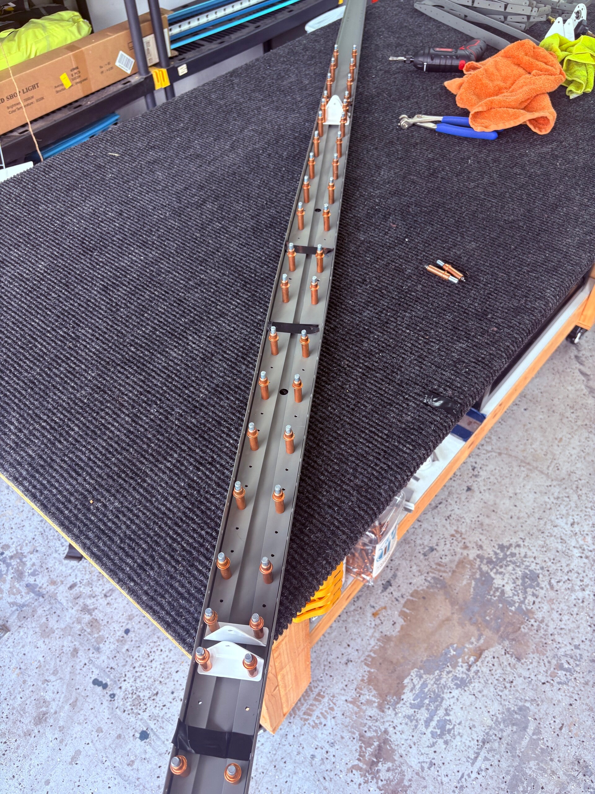
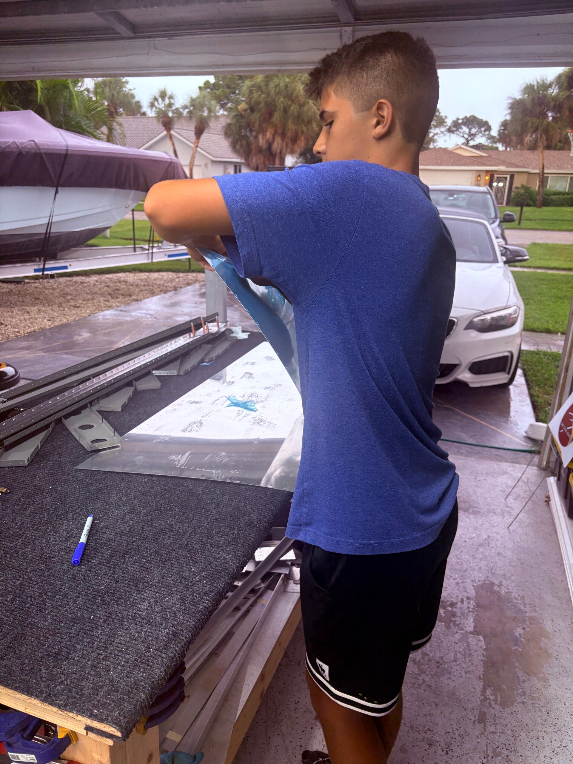
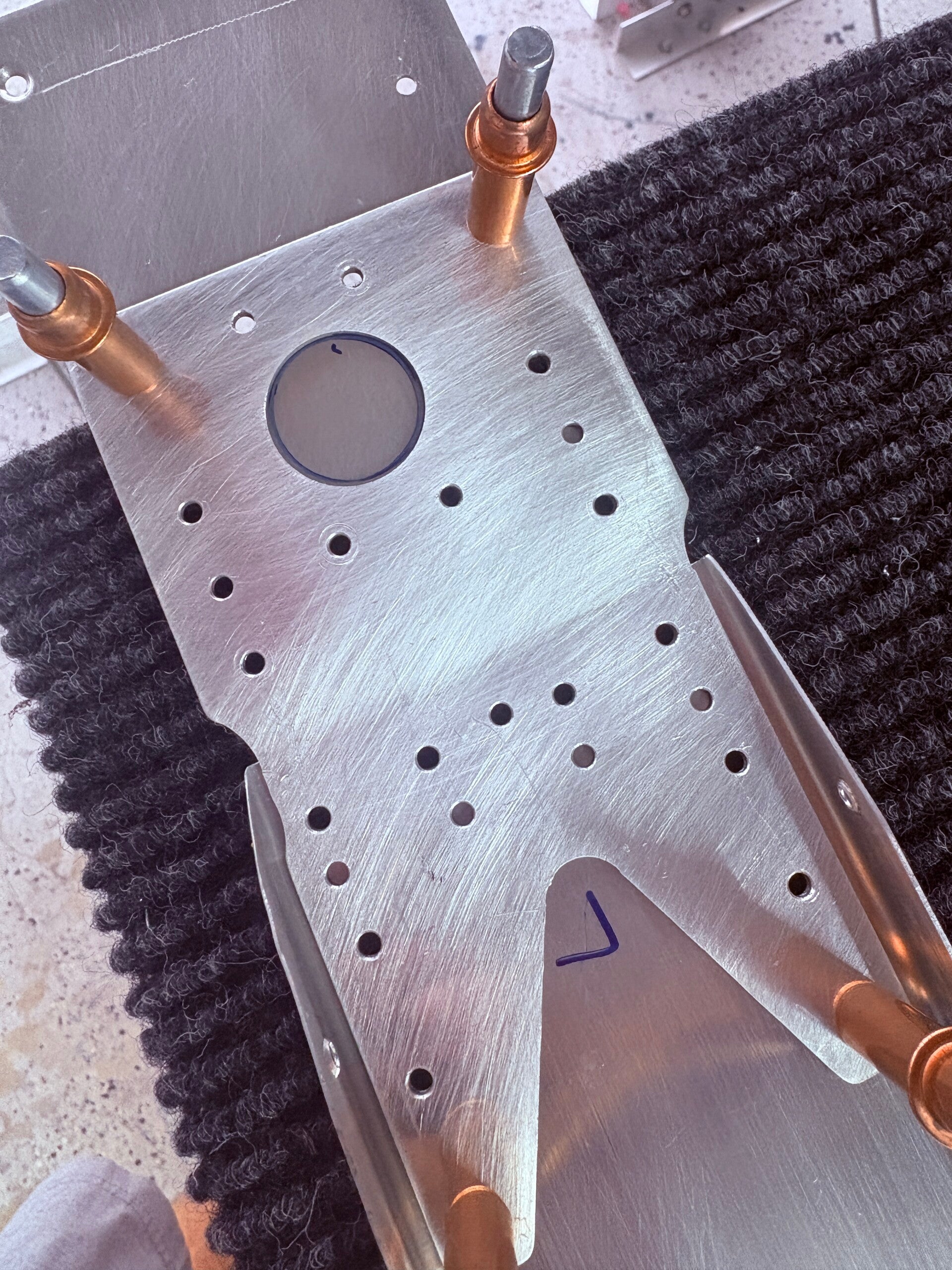
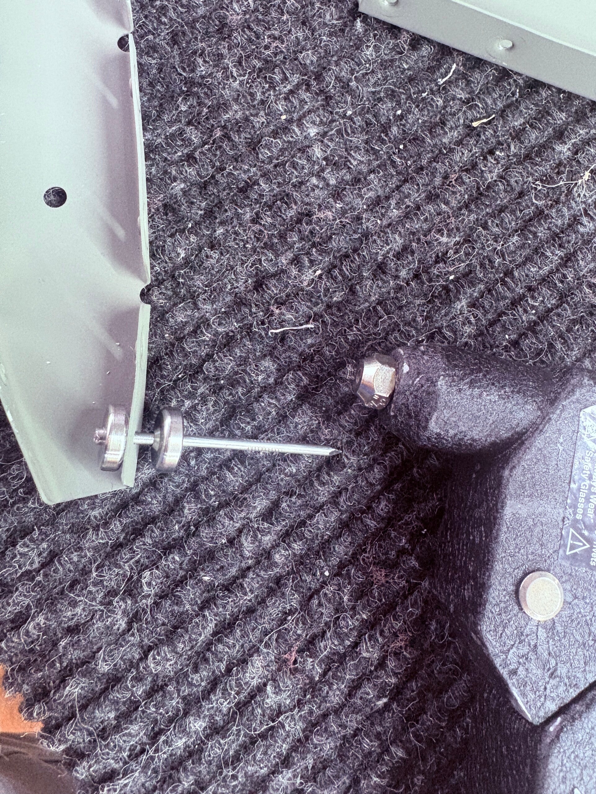
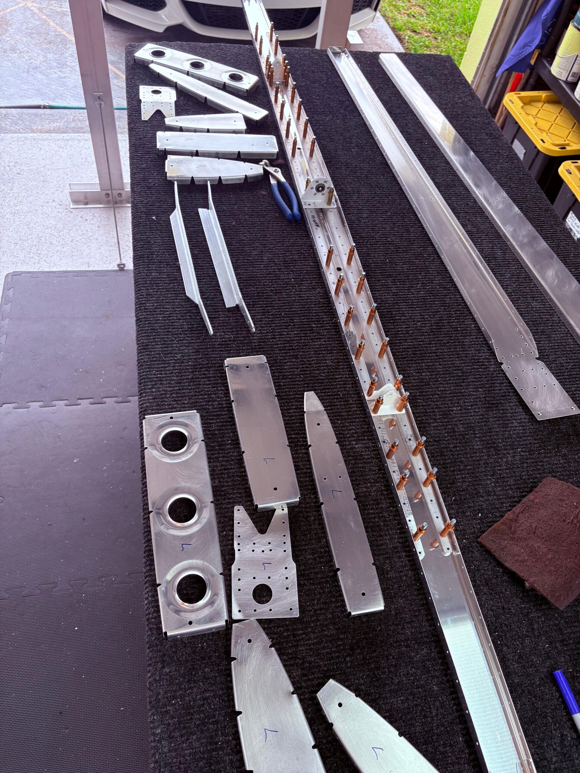
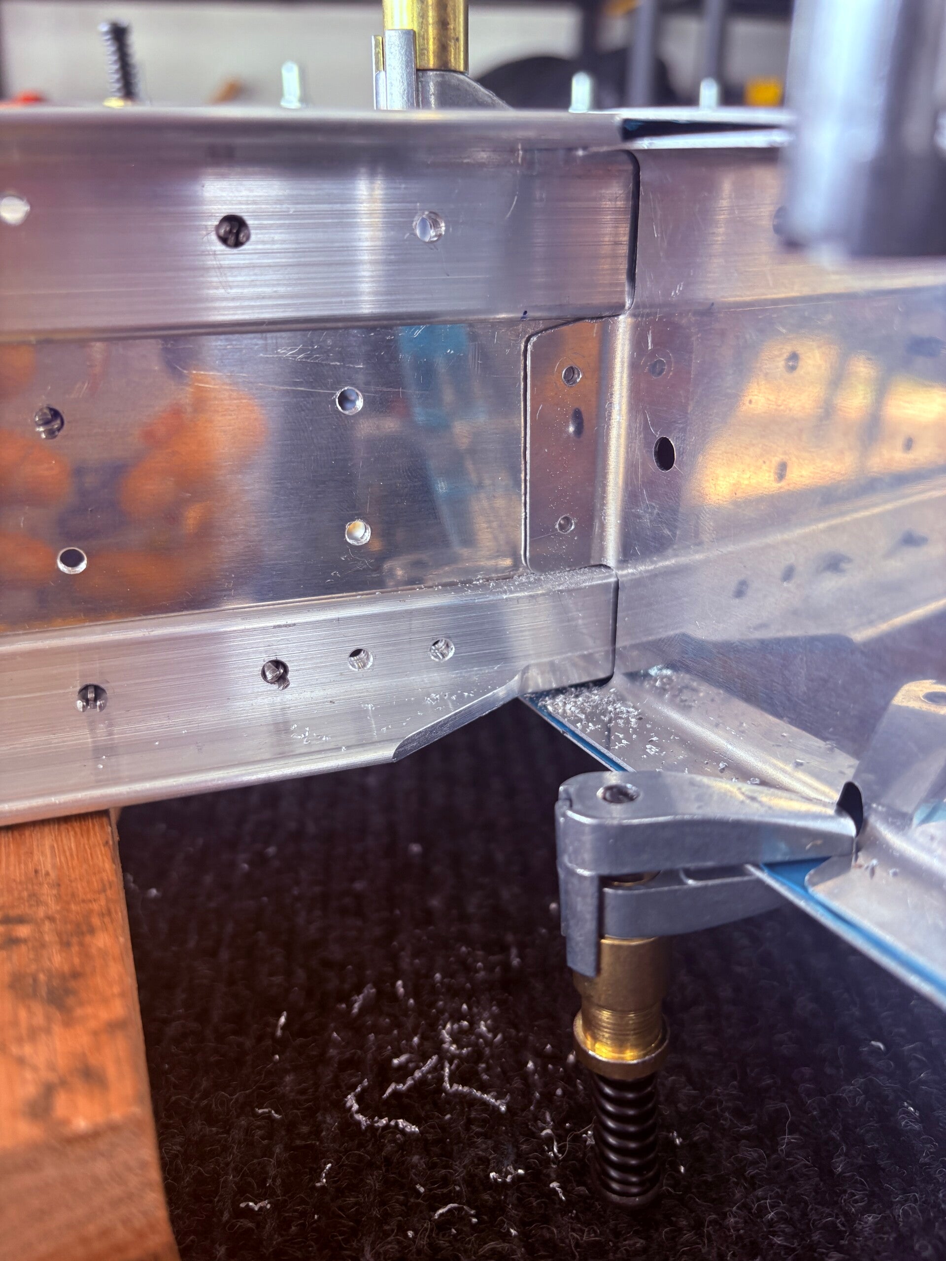
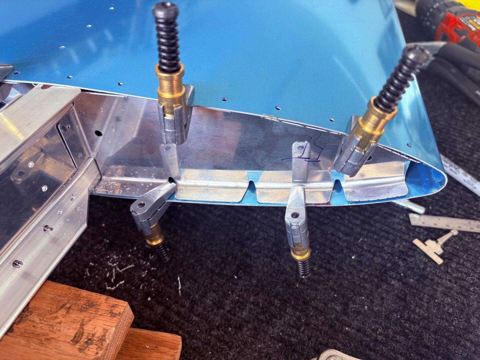
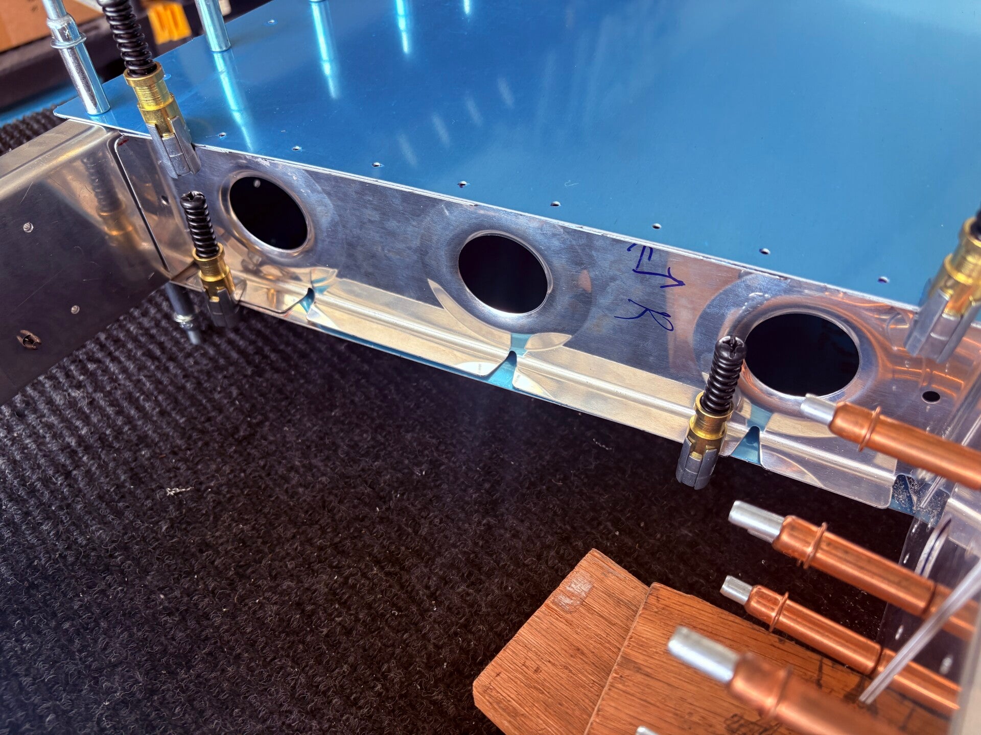
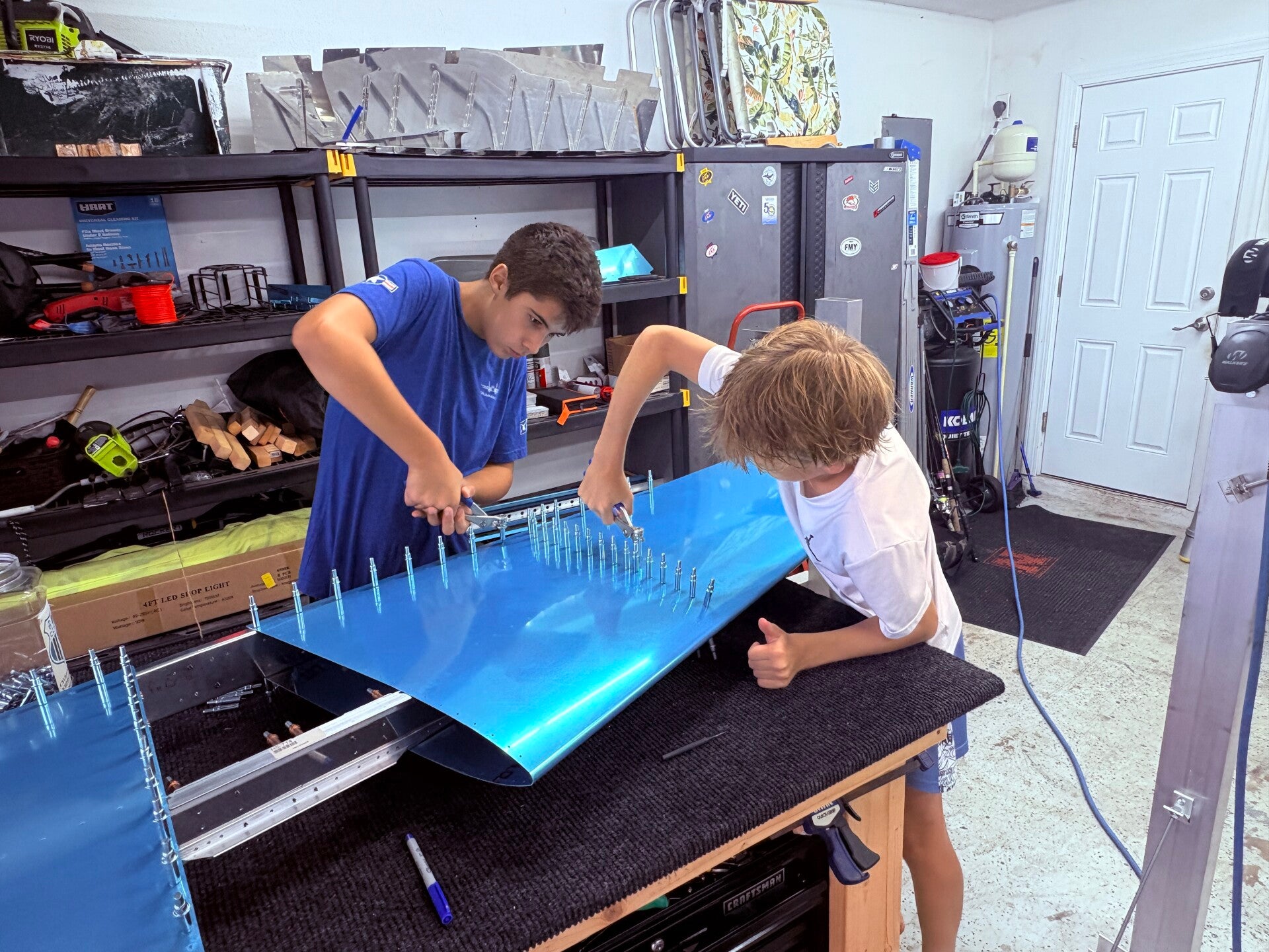
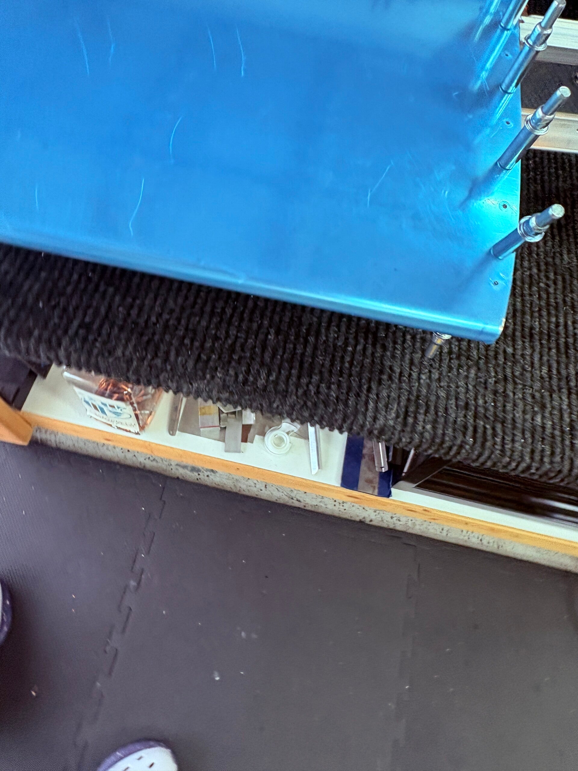
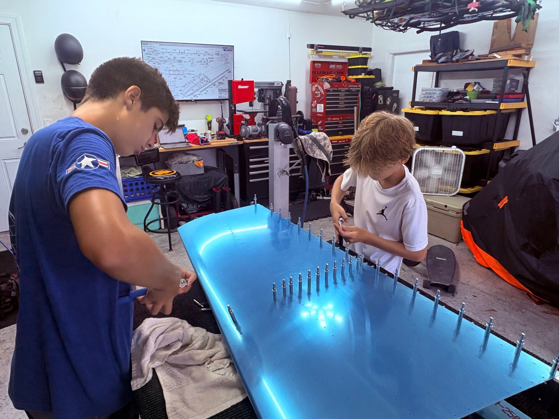
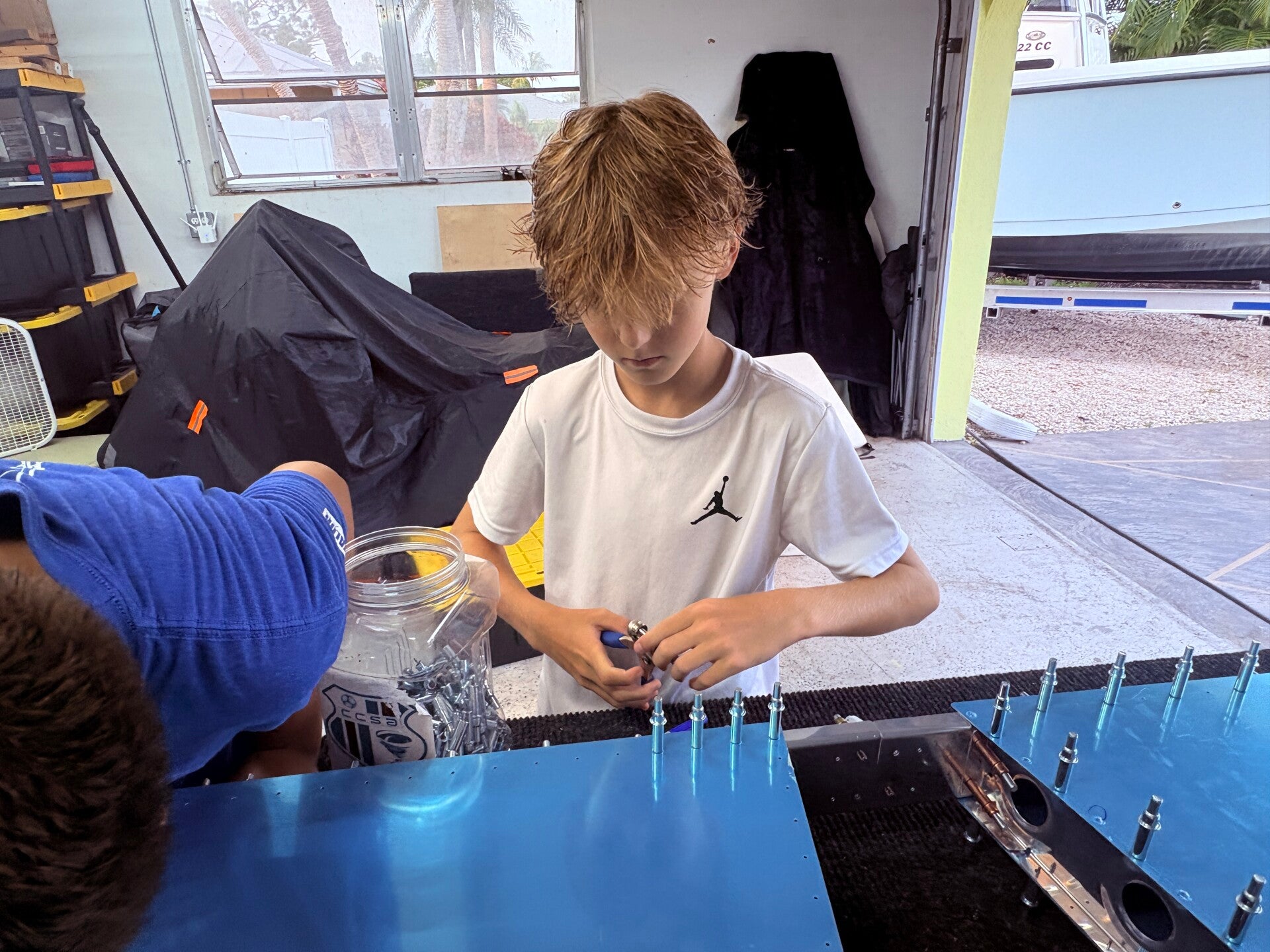
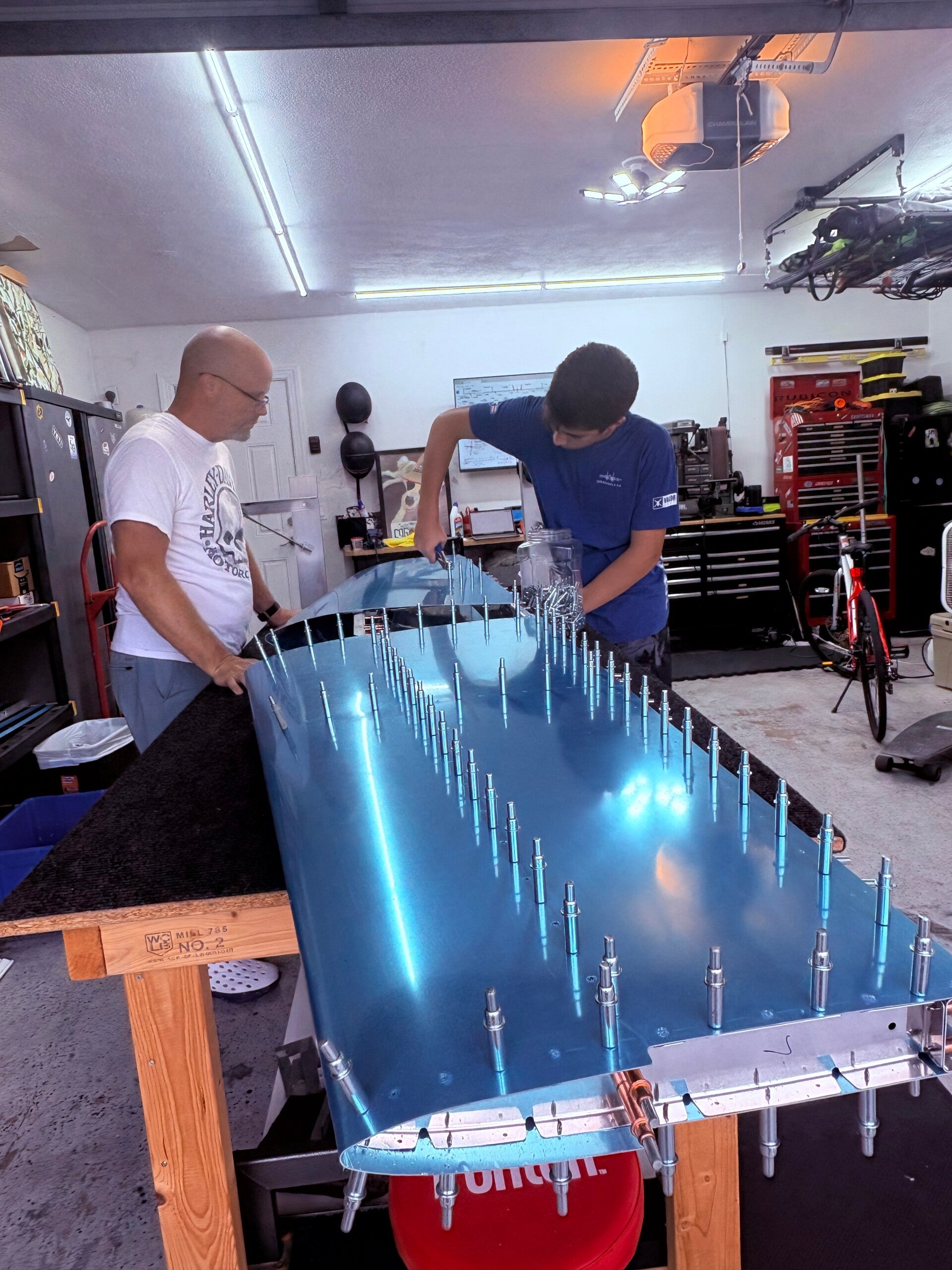
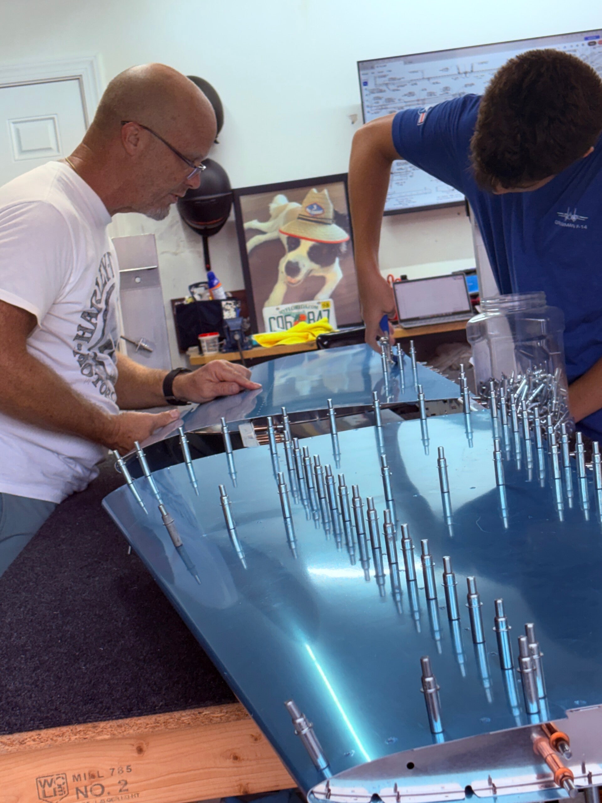
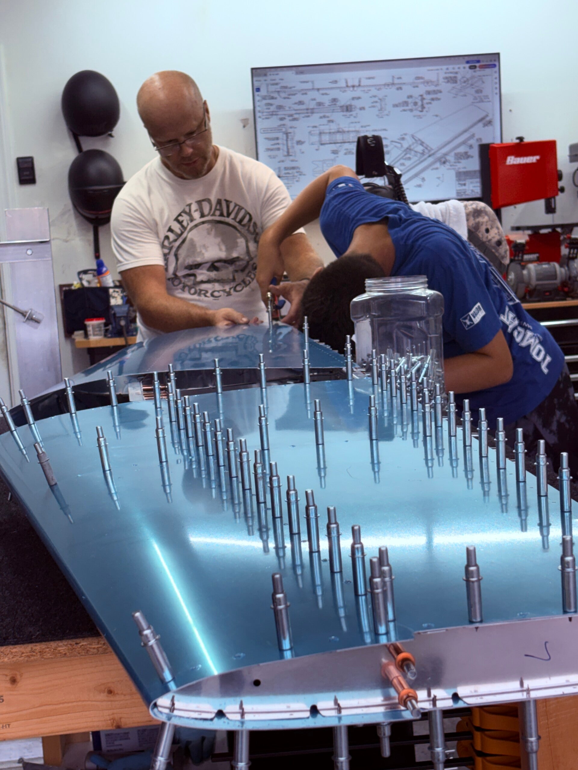
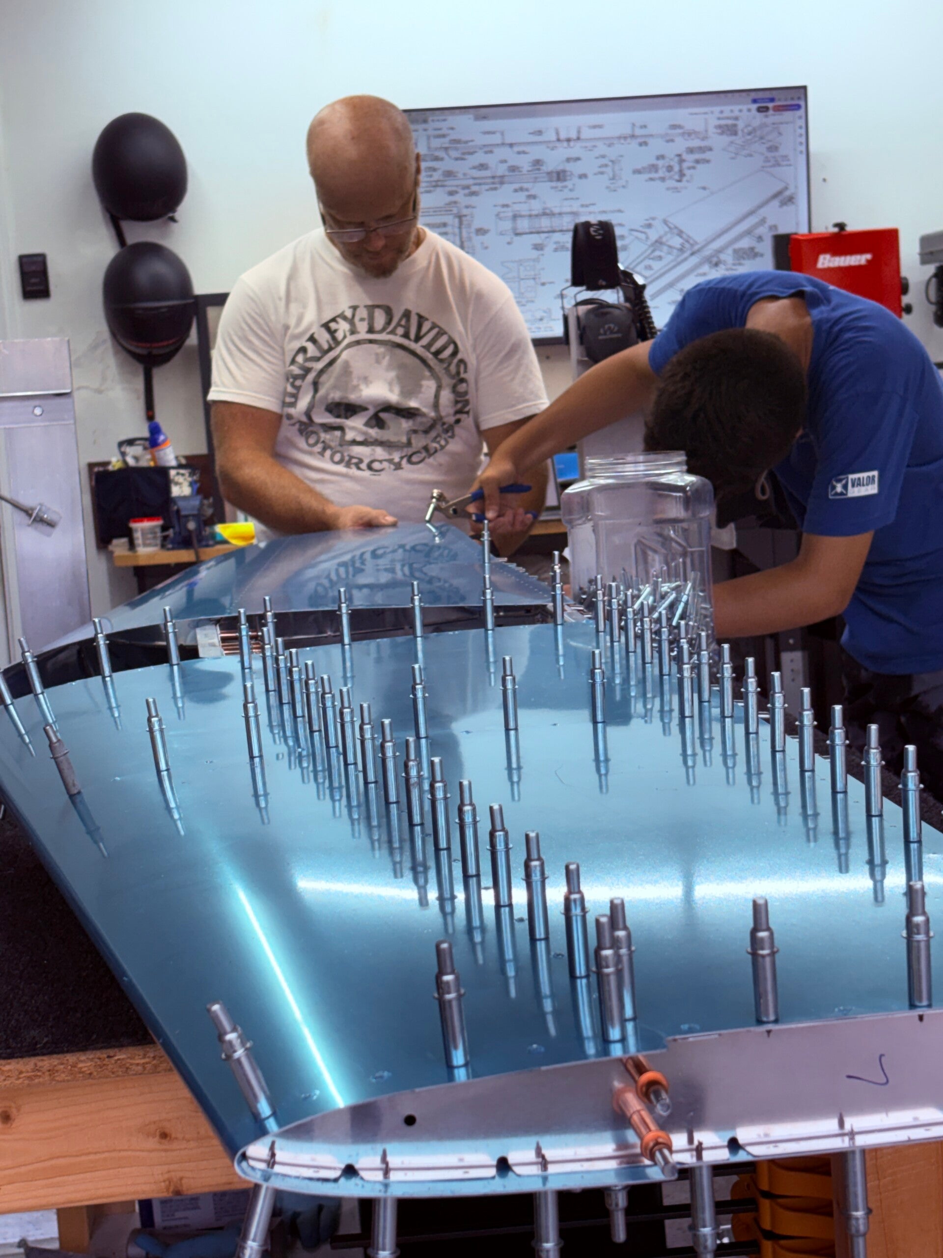
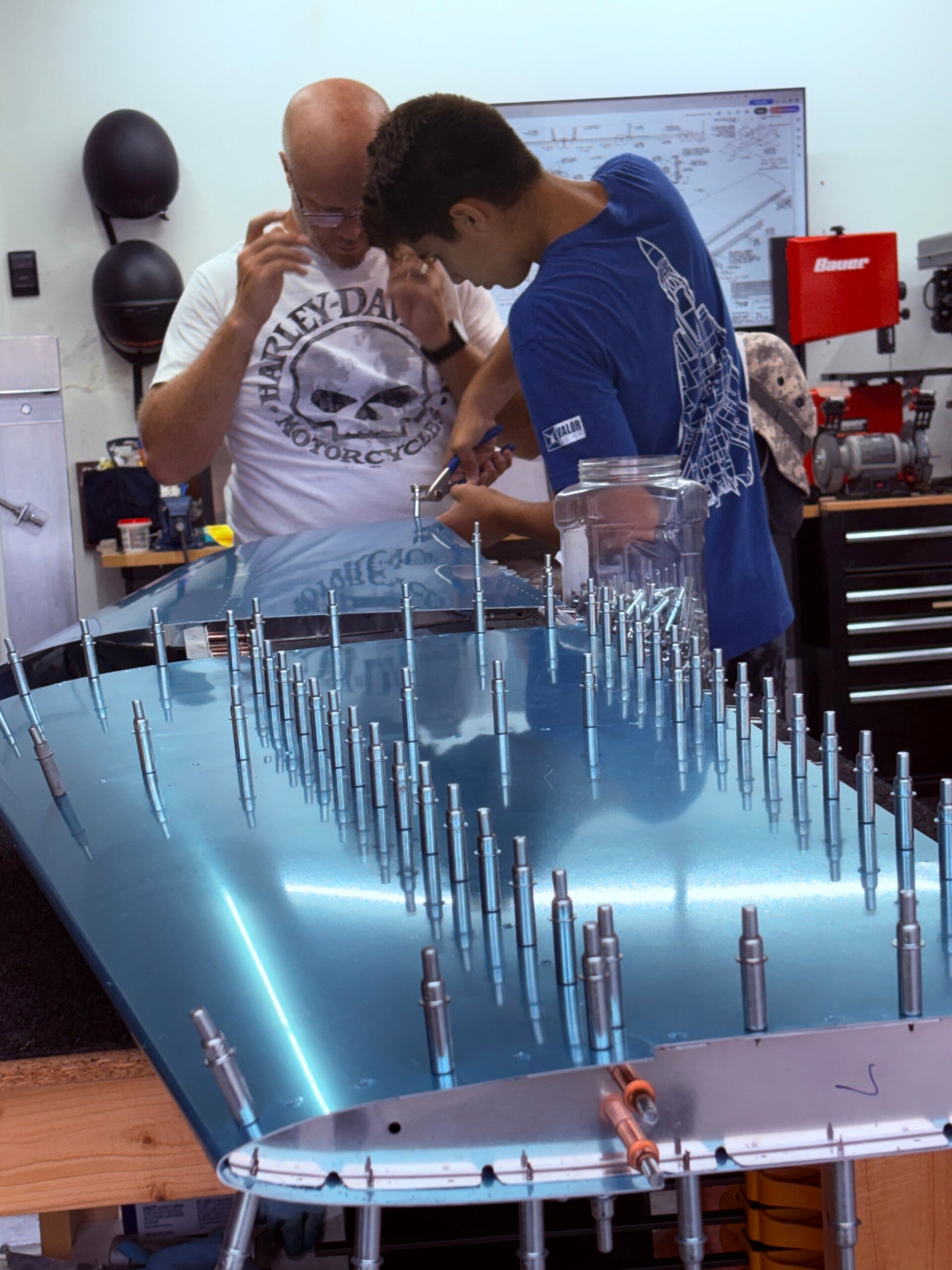
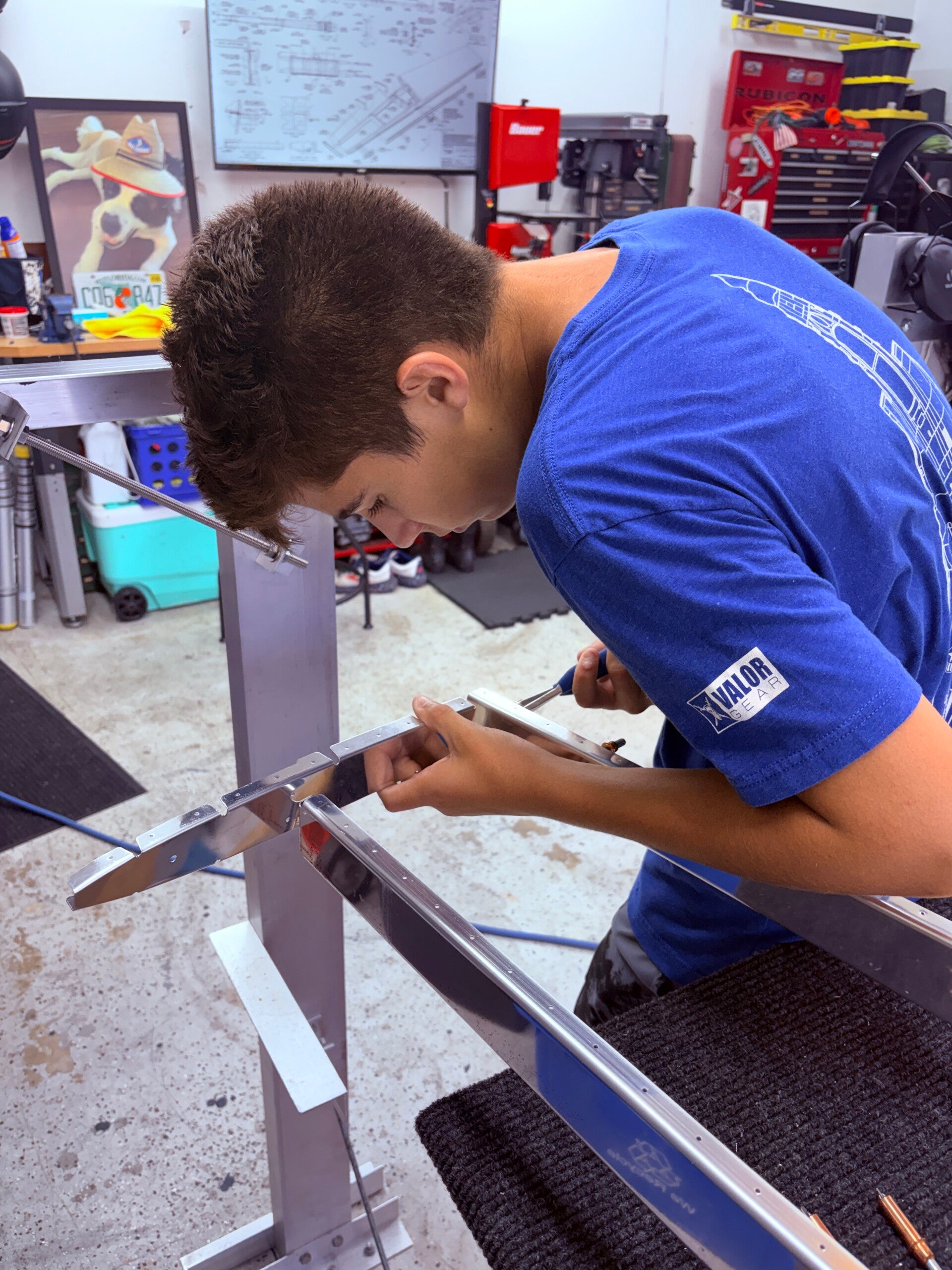
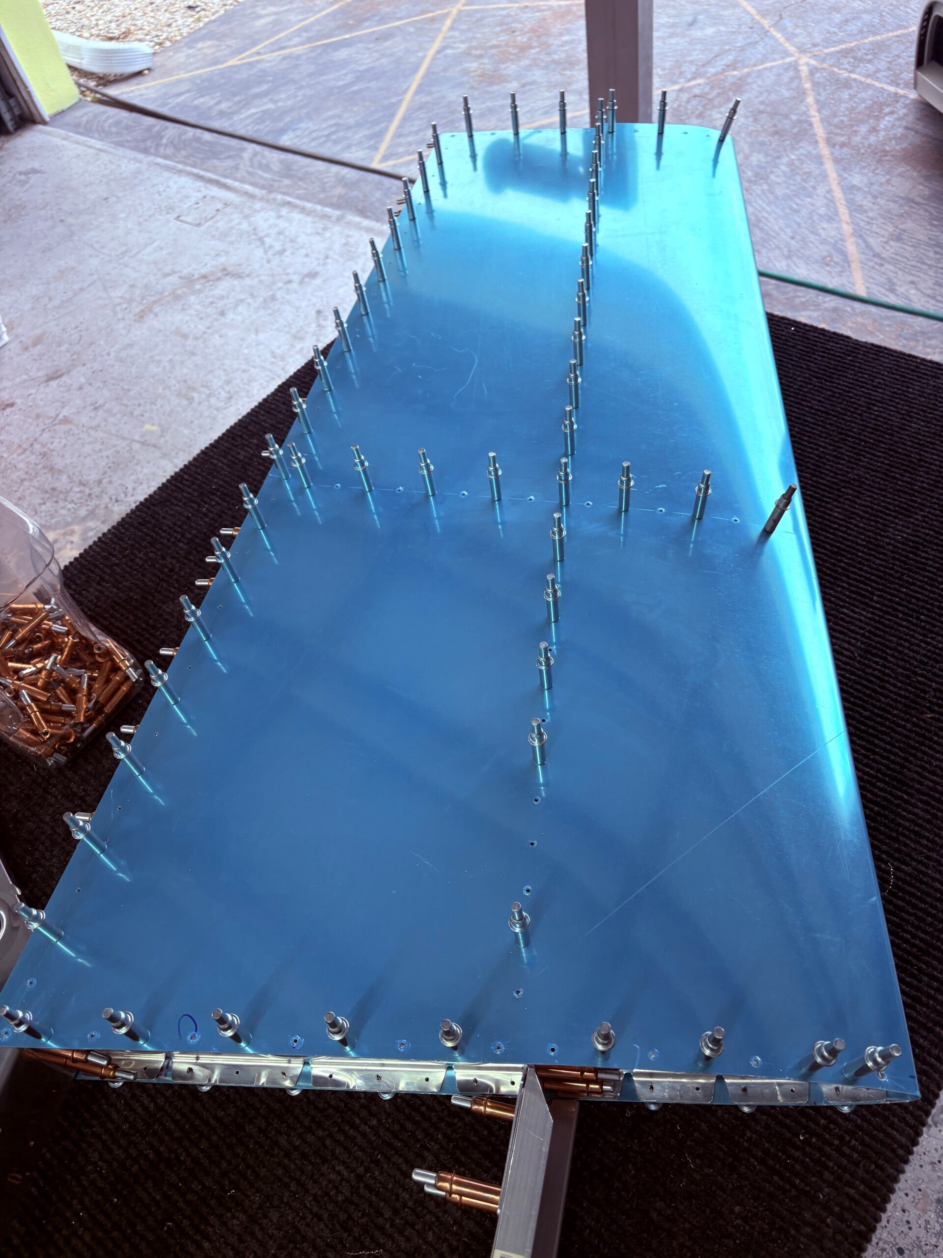
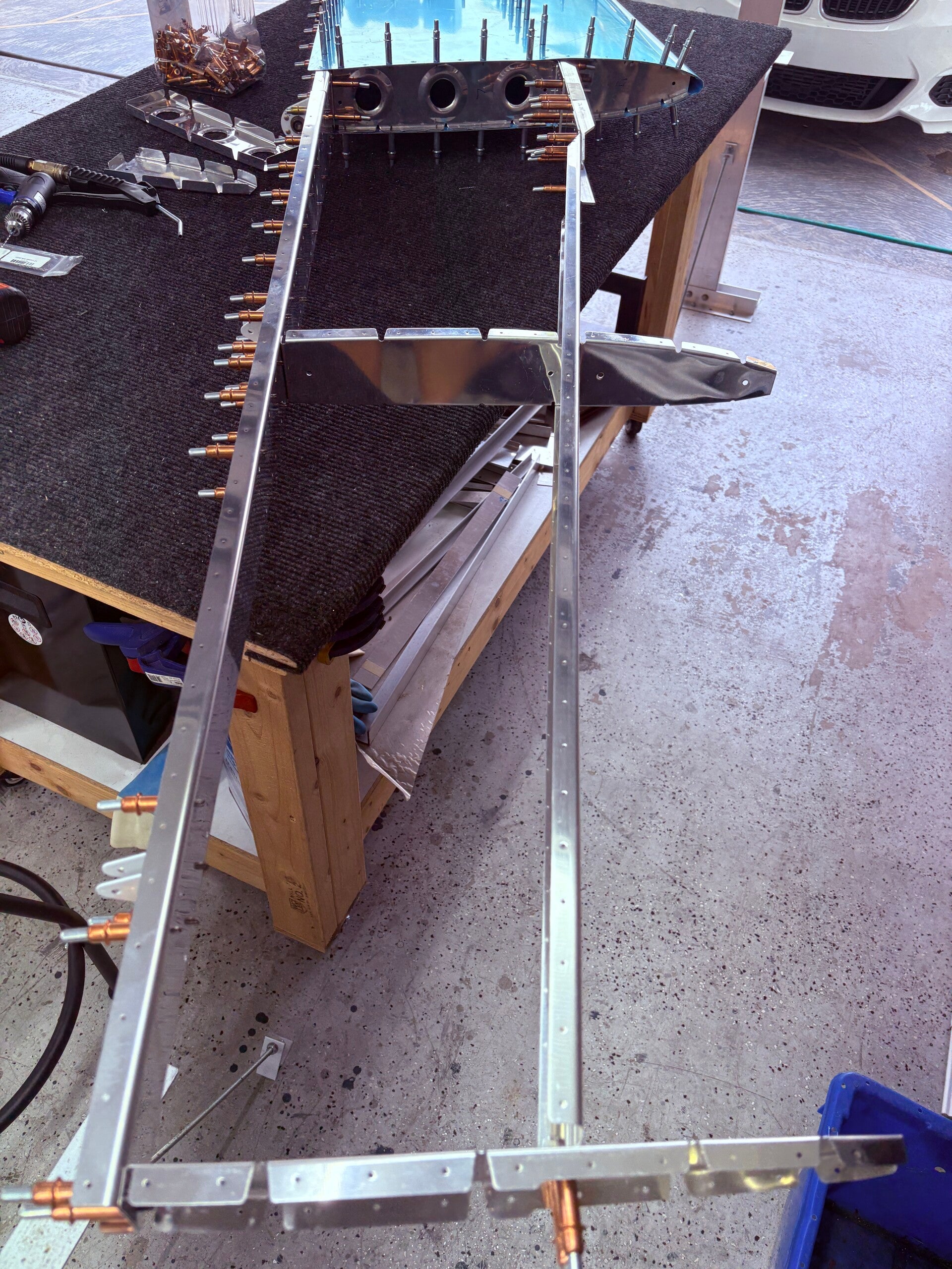
8/24/2026 (10 hours)
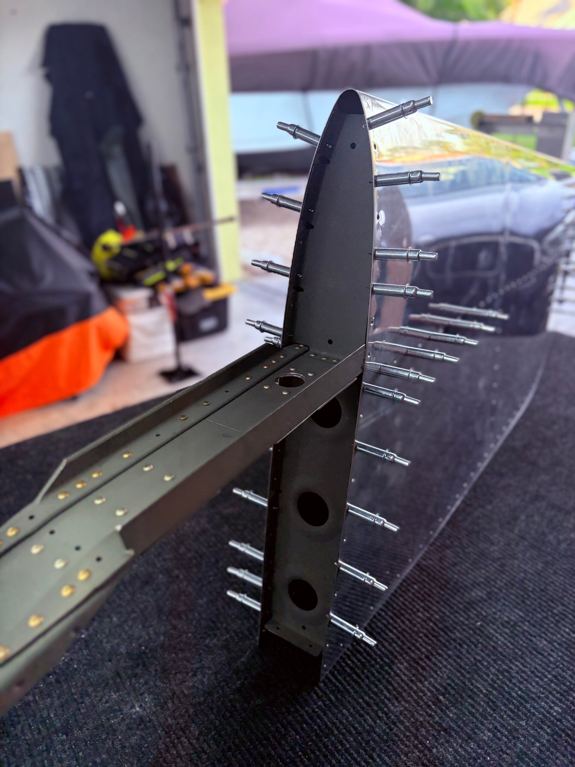
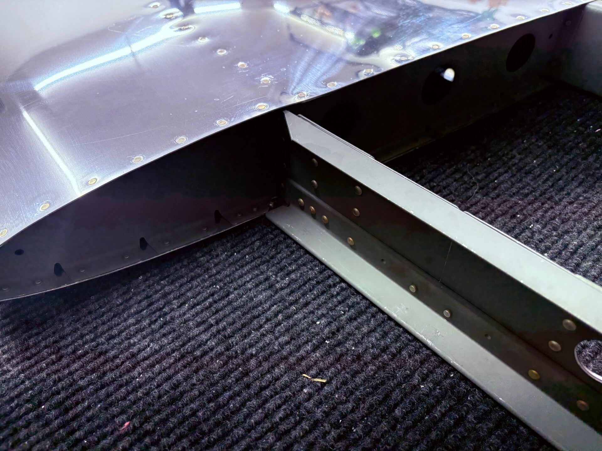
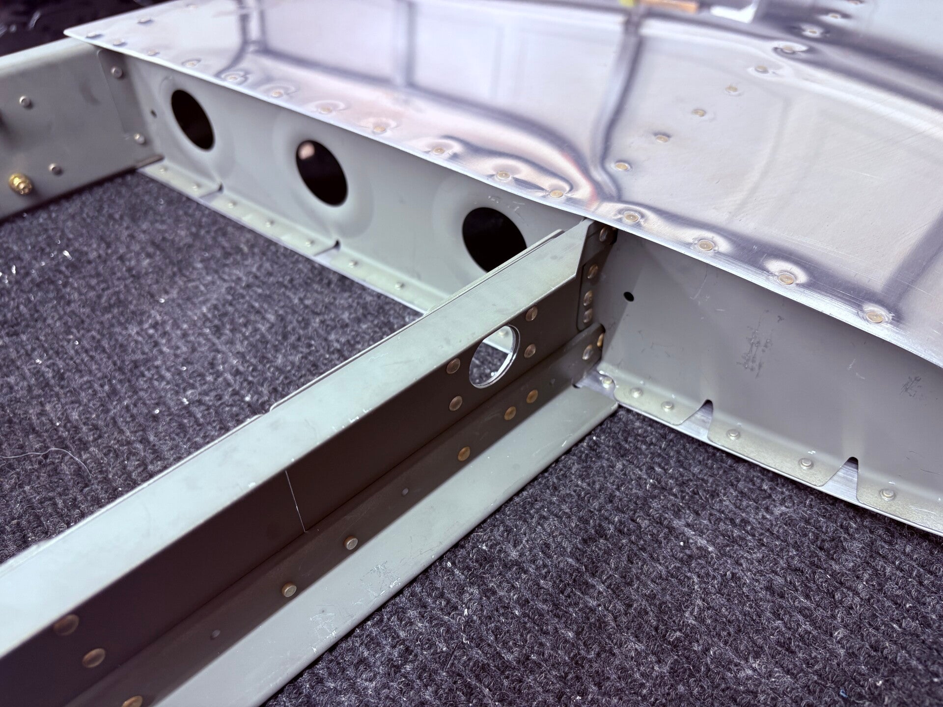
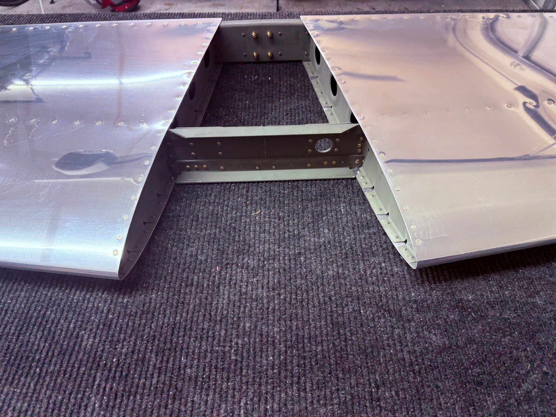
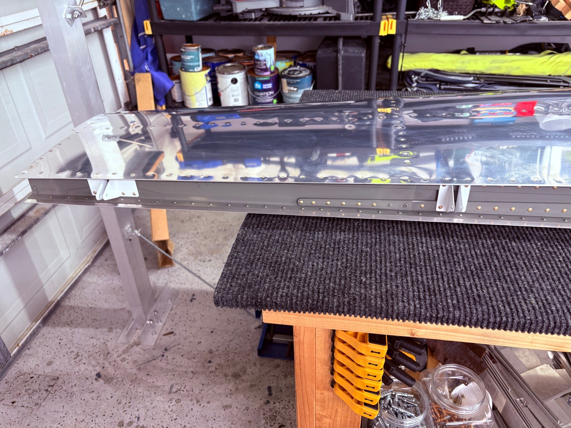
Repeated the above steps for the right side then clecoed on the rear spar assembly.
Riveted the rear spar assembly, HS-00006, HS-00005, and HS-706 to HS-601PP.
Blind rivet the rear spar assembly to HS-708.
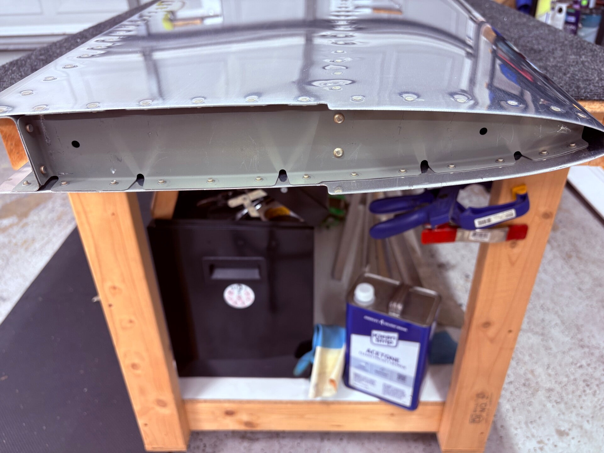
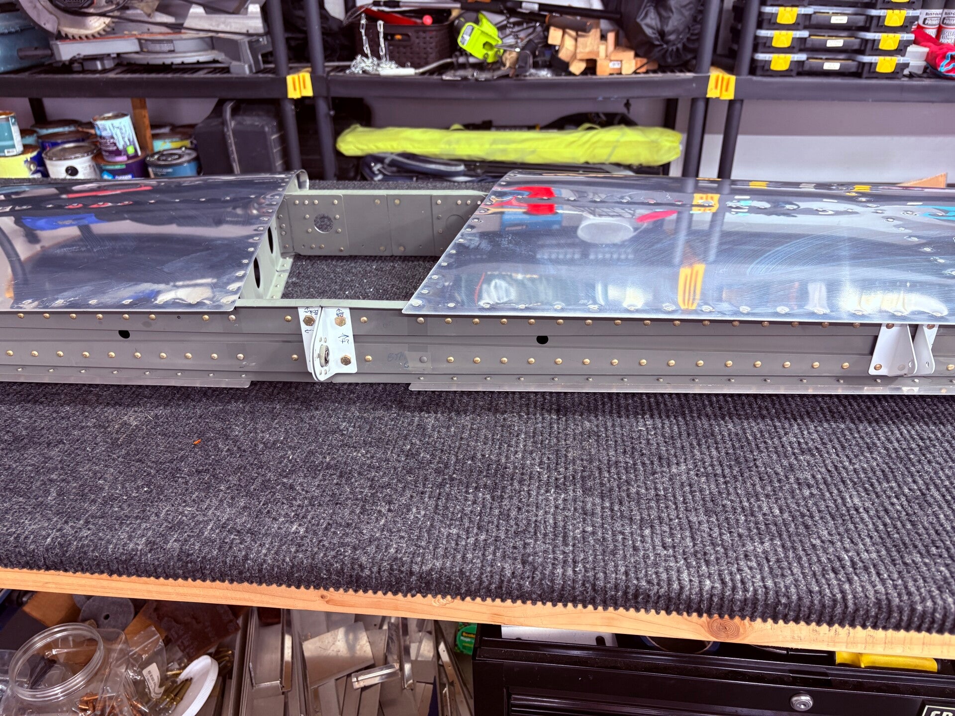
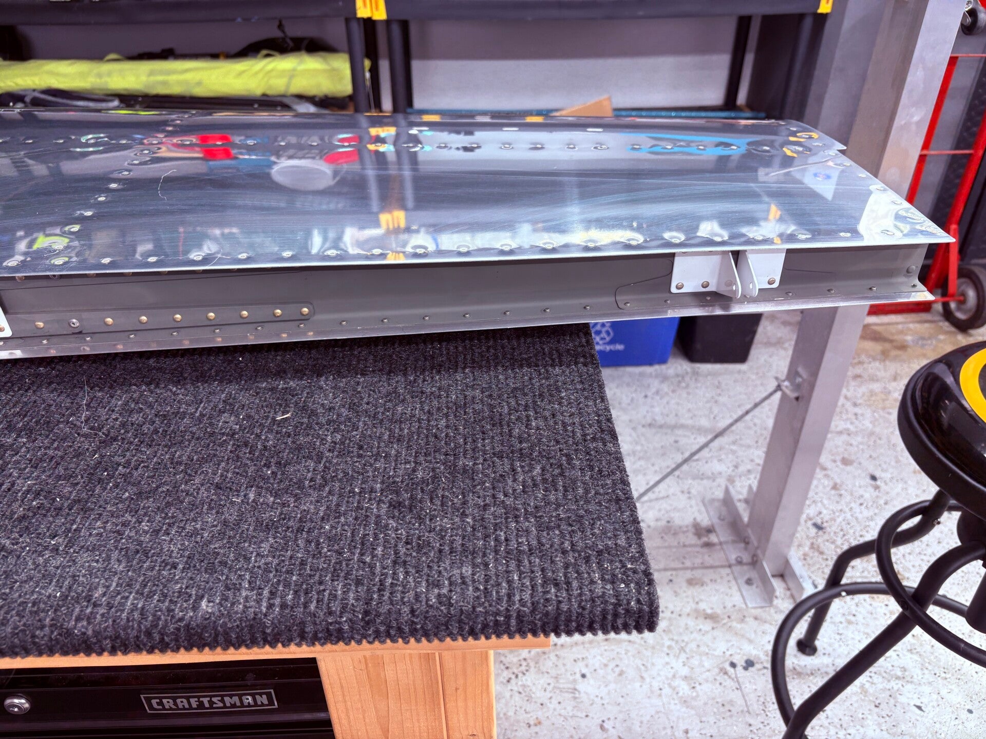
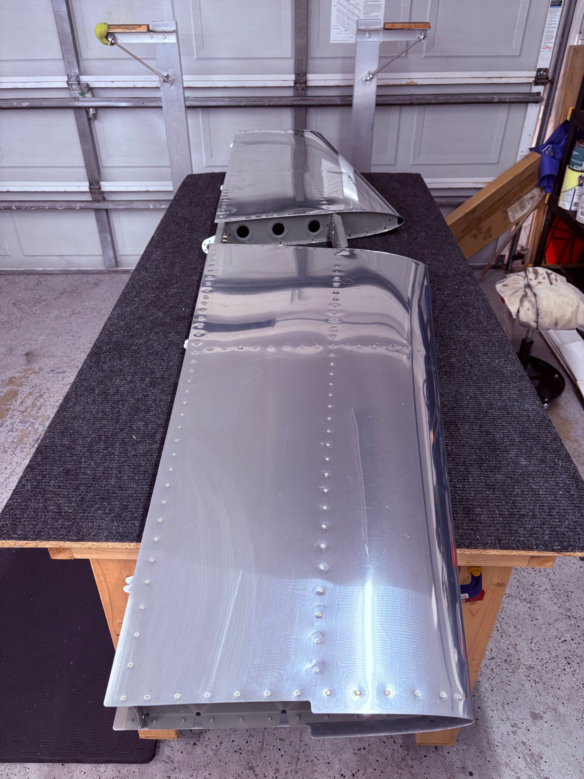
Vertical Stabilizer - COMPLETE
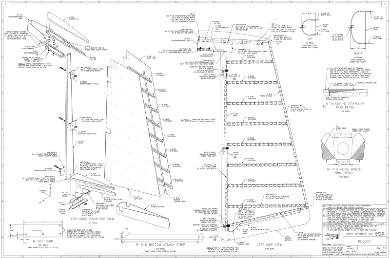
4/11/2026 (2 hours)
Skeleton
Manual section 6-5
Steps 1-7
Skeleton assembly, skin fitting, fluting, all drilling of ribs. Skin match drilling will come next.
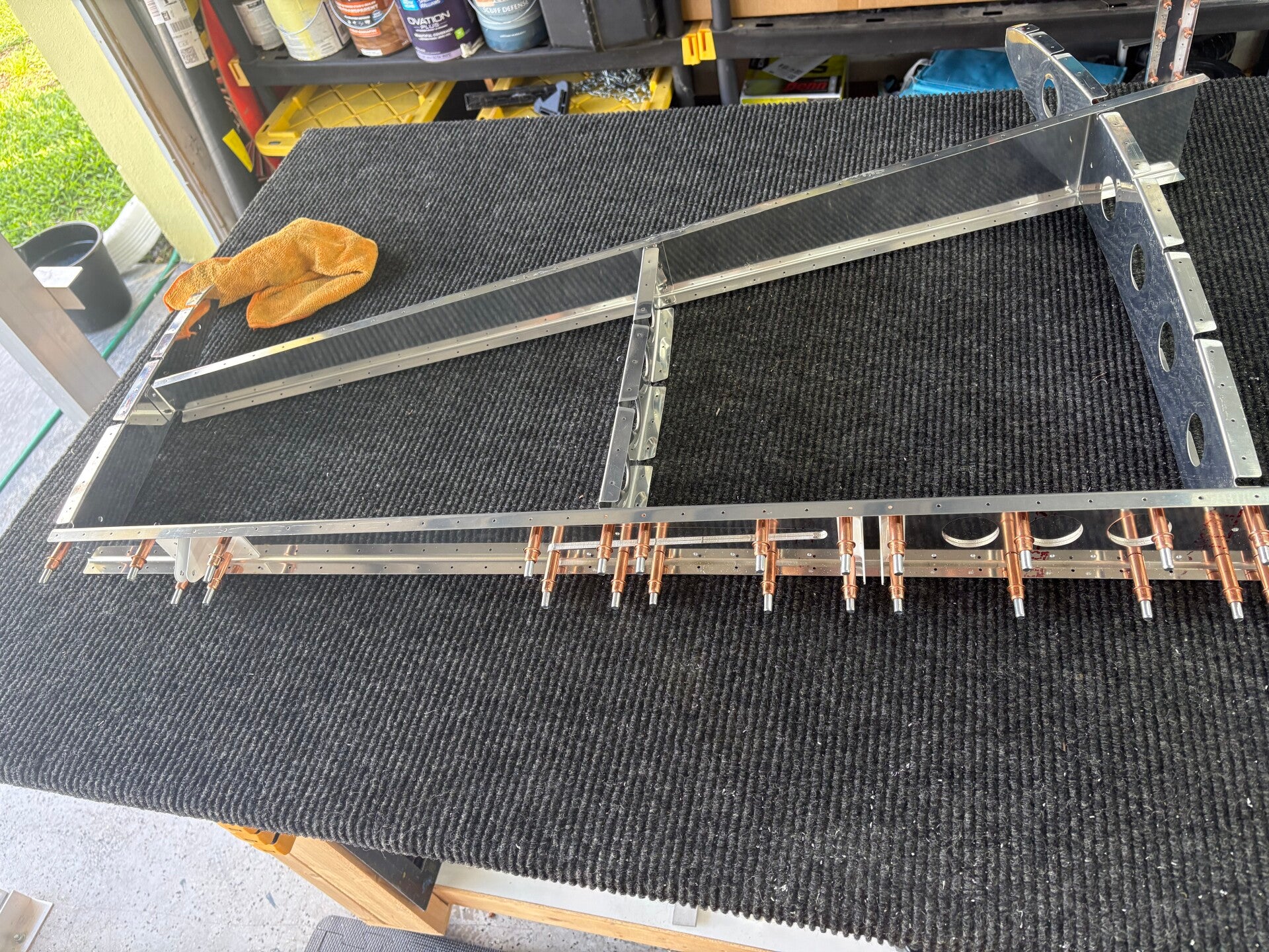

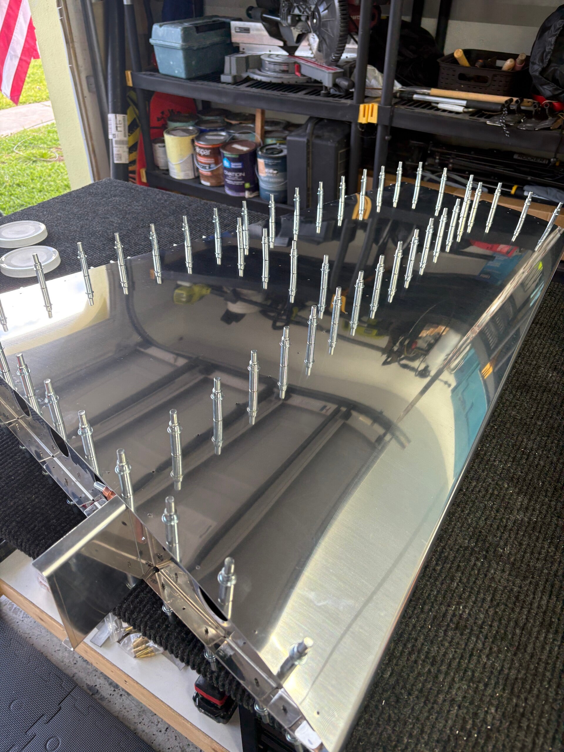
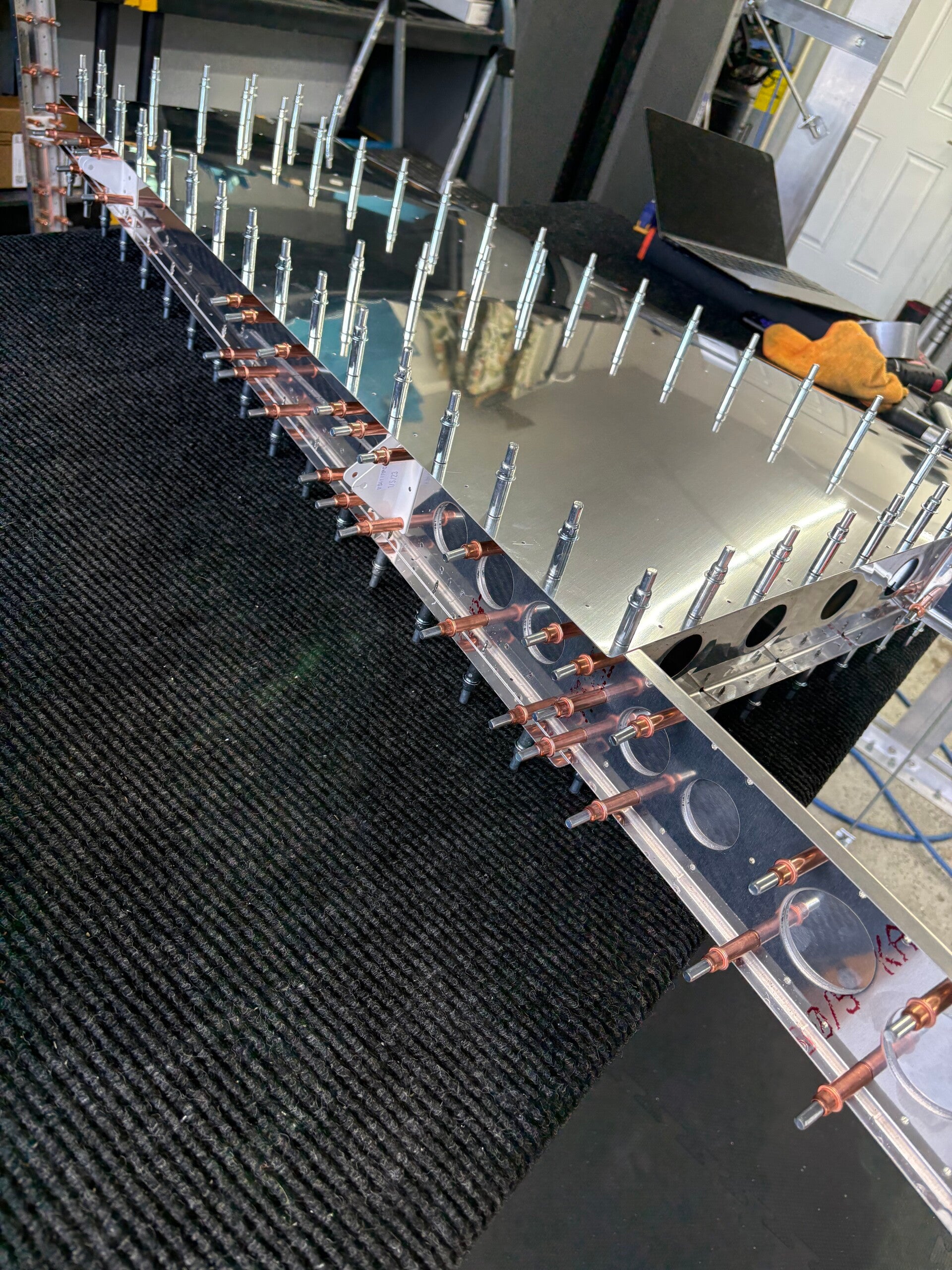
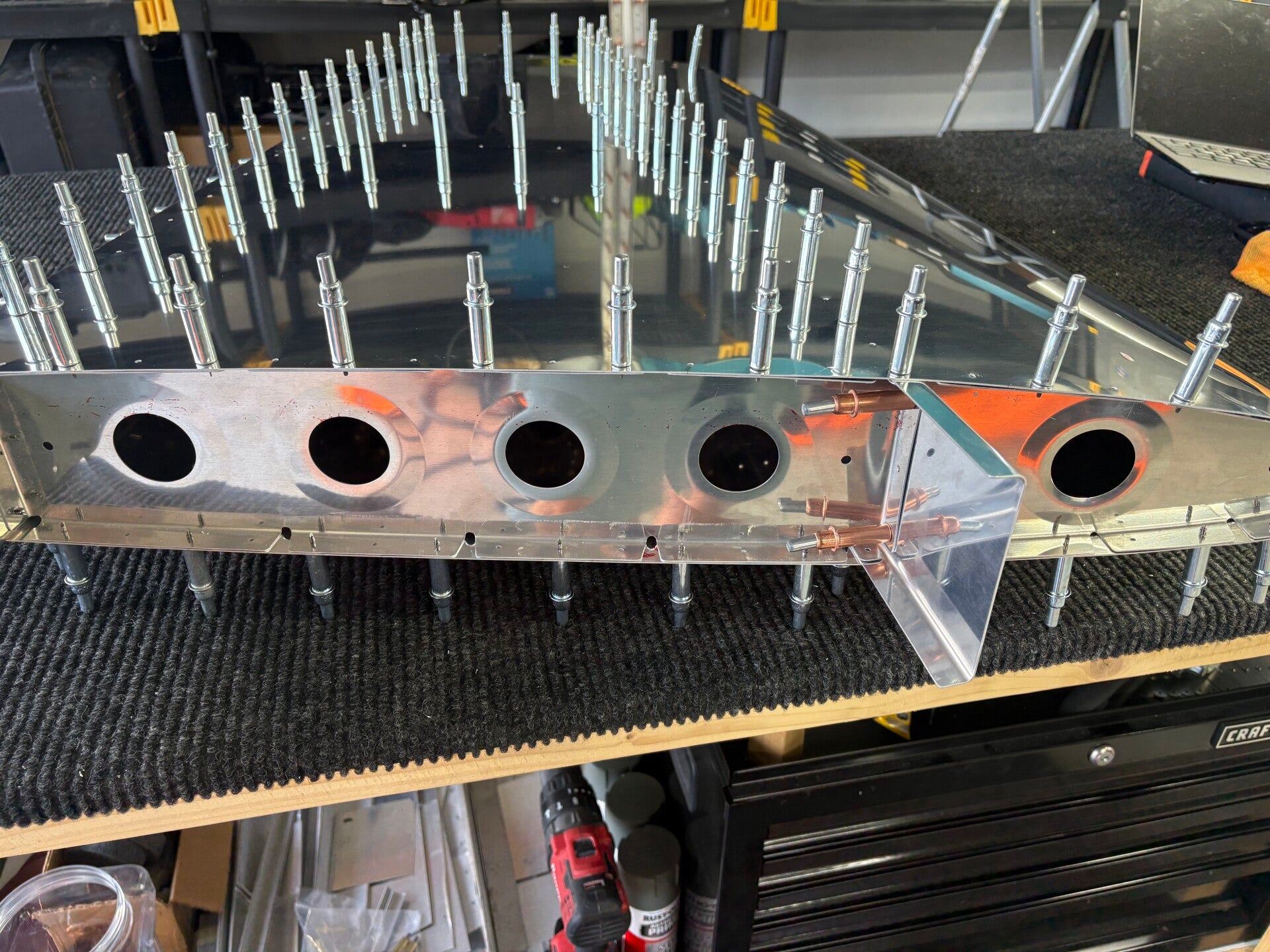

4/12/2026 (6.5 hours)
Manual section 6-5
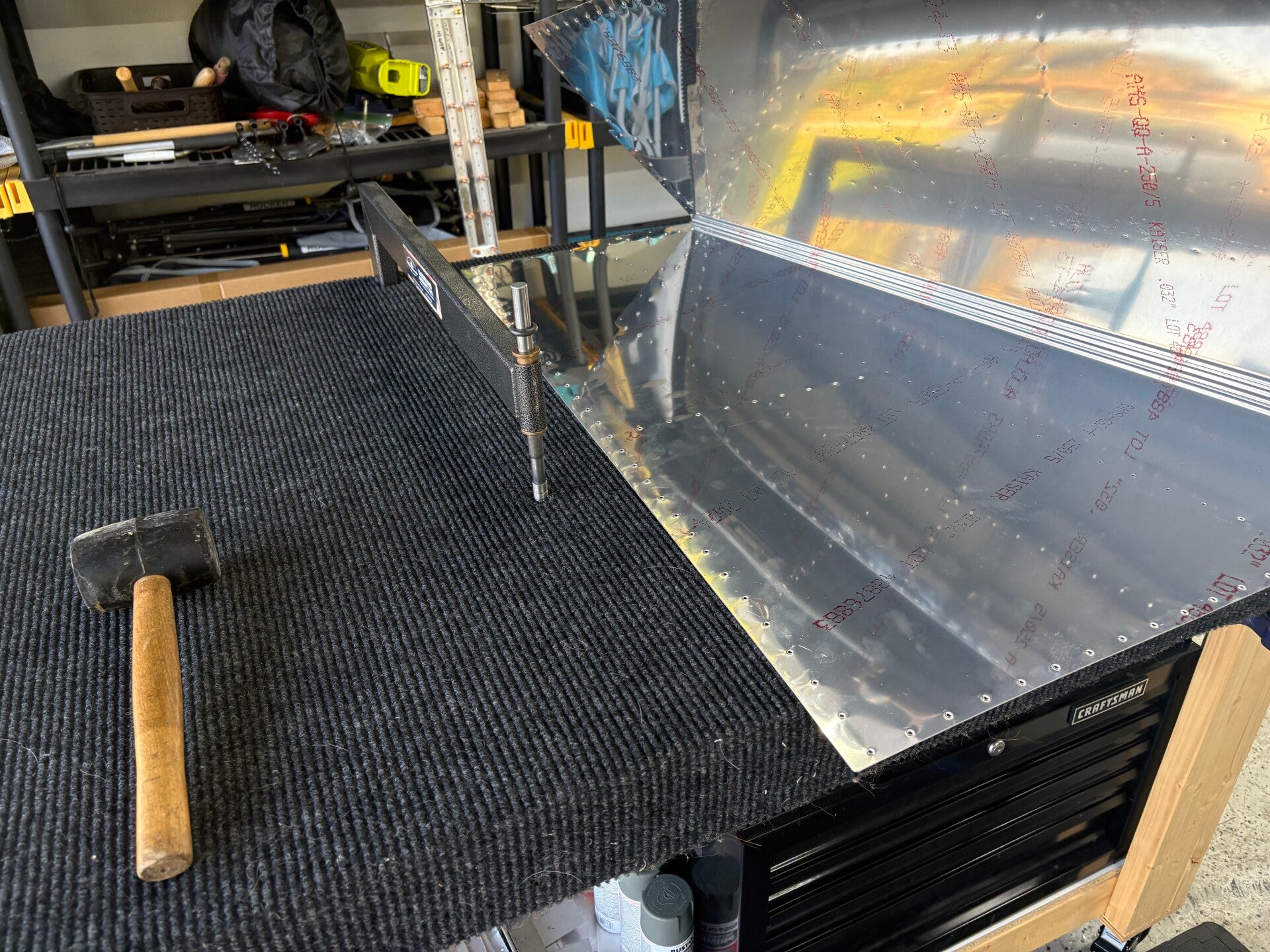
Match drilled skin to skeleton, deburrred all, dimpled skeleton and most of skins. Will complete on the c-frame dimpler once I get a new spring for it. Prepped skeleton for priming.
4/14/2026 (2 hours)
Manual section 6-5
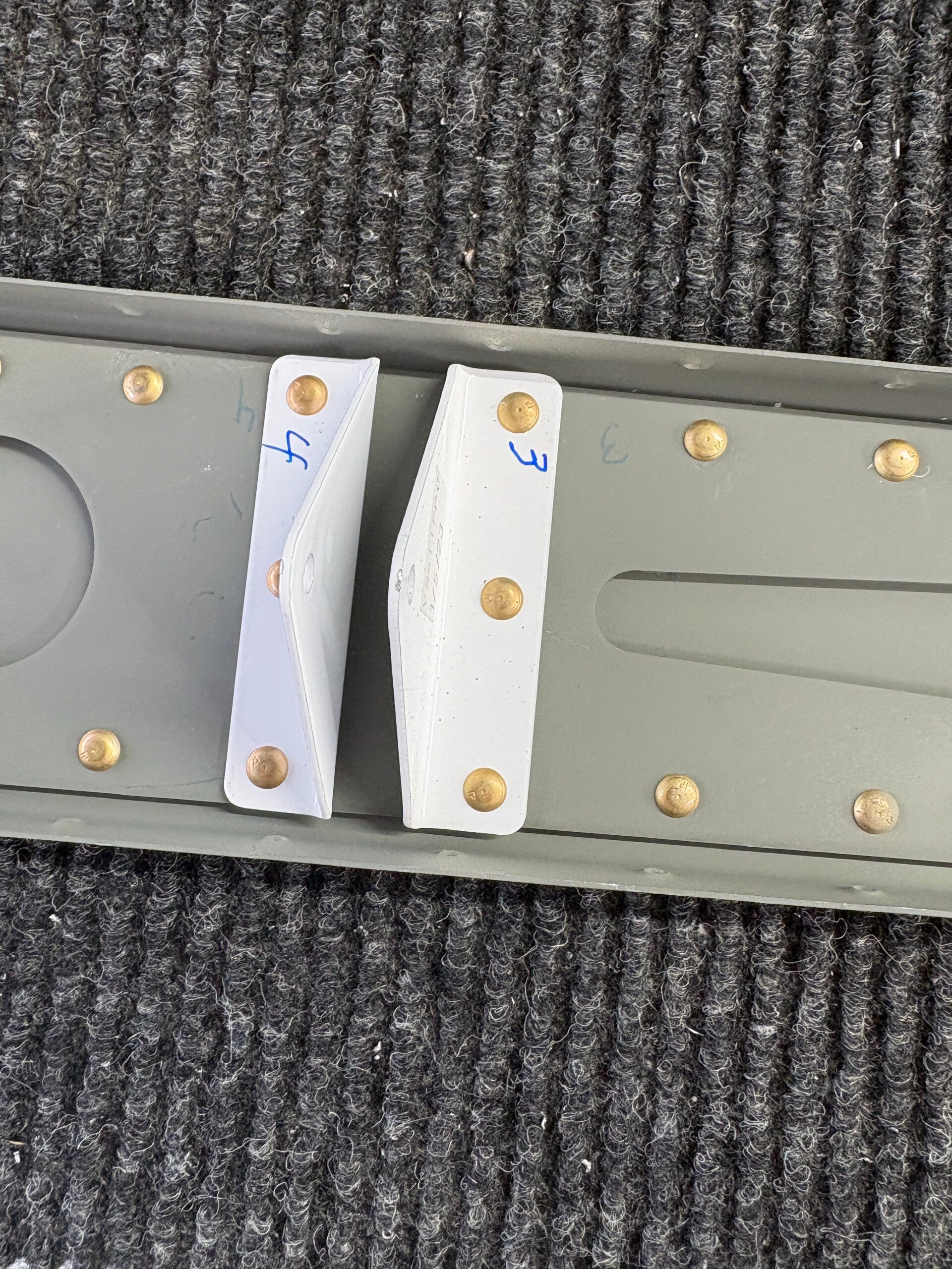
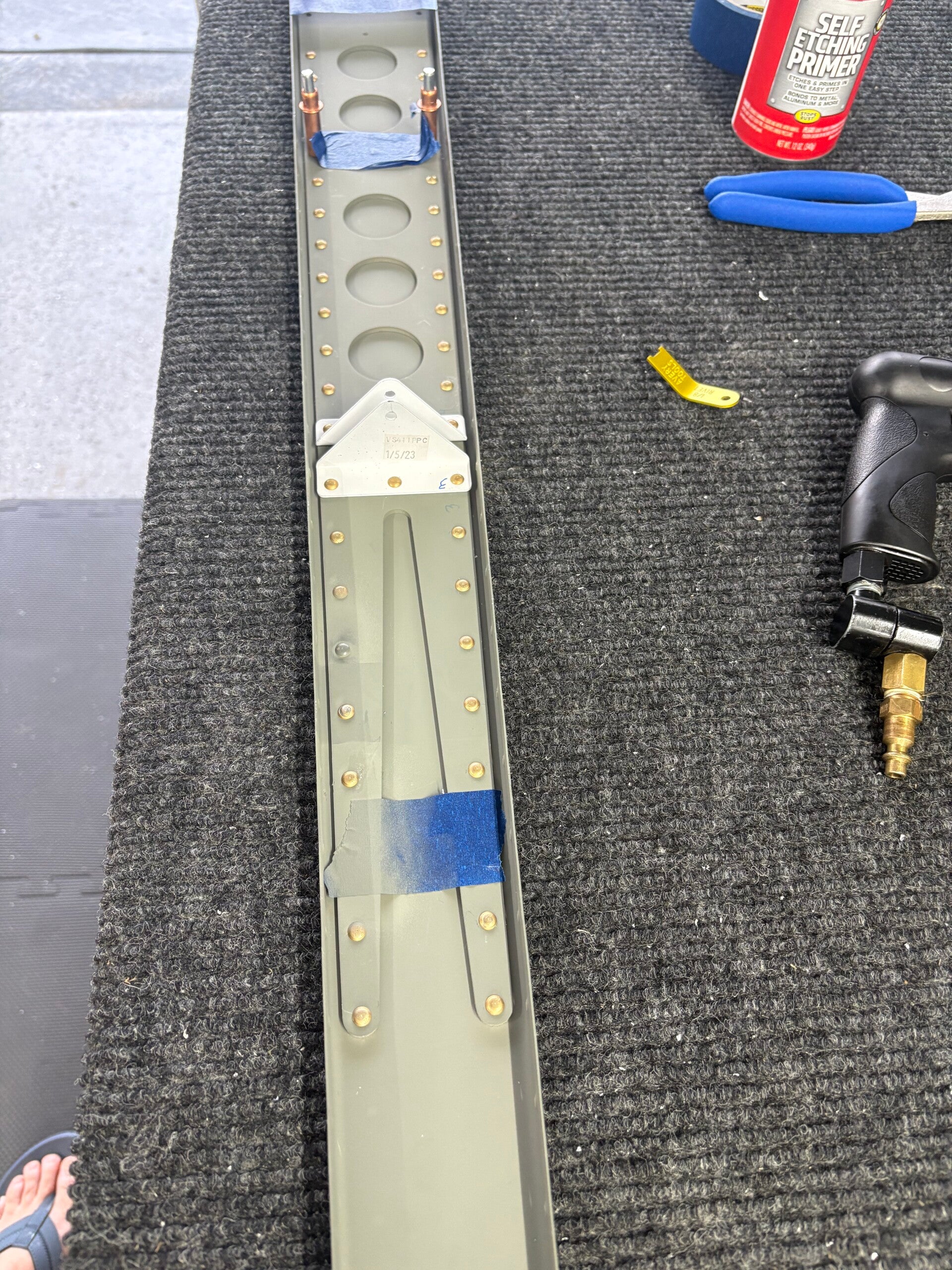
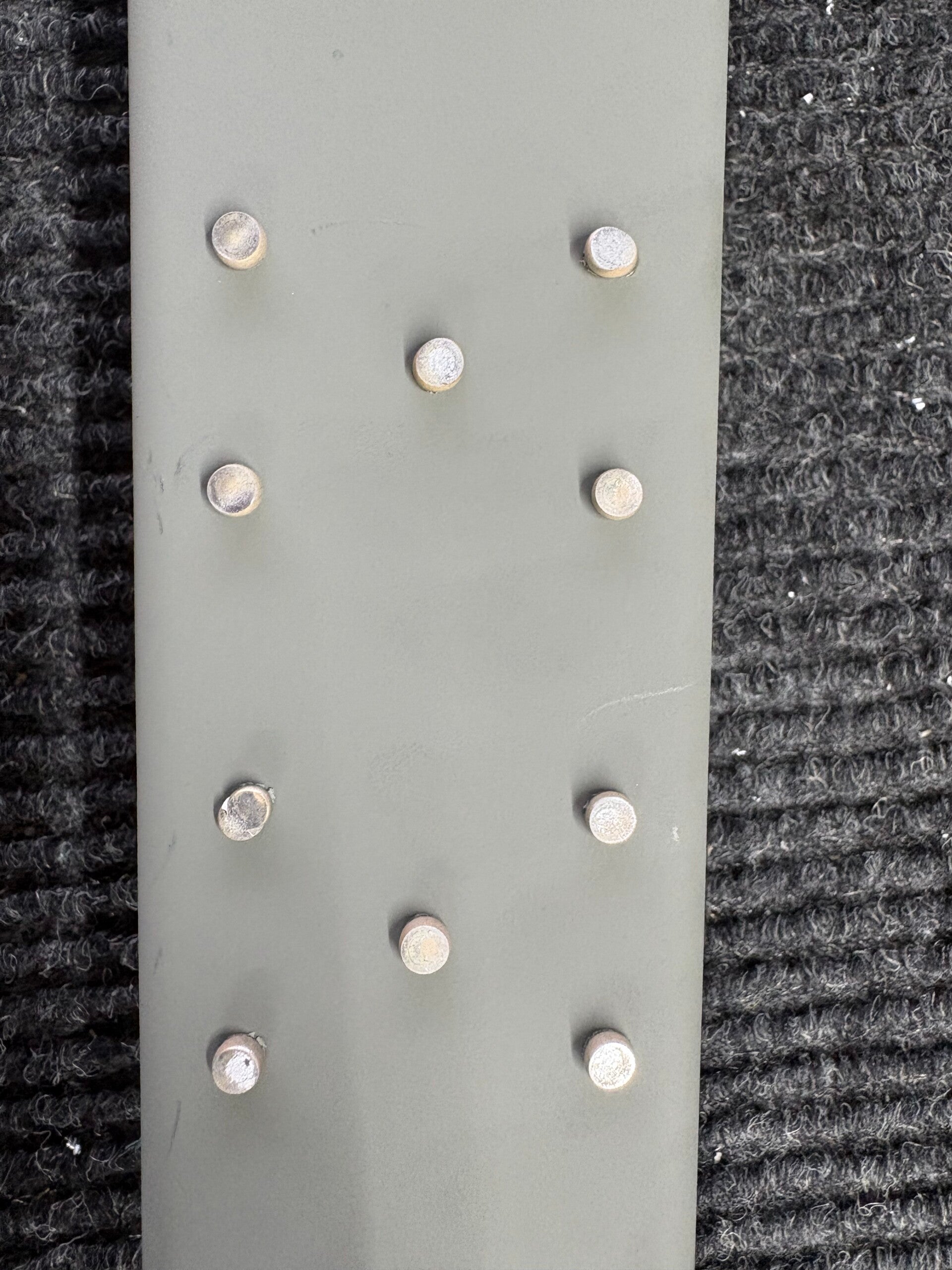
Finished skin dimpling with Gunnar. Started VS rear spar riveting. We had a couple of bad rivets that needed drilled out and set again but all in all ... went well. Gunnar learned quite a bit today!

4/15/2026 (2 hours)
Manual section 6-5
Steps 1-4.
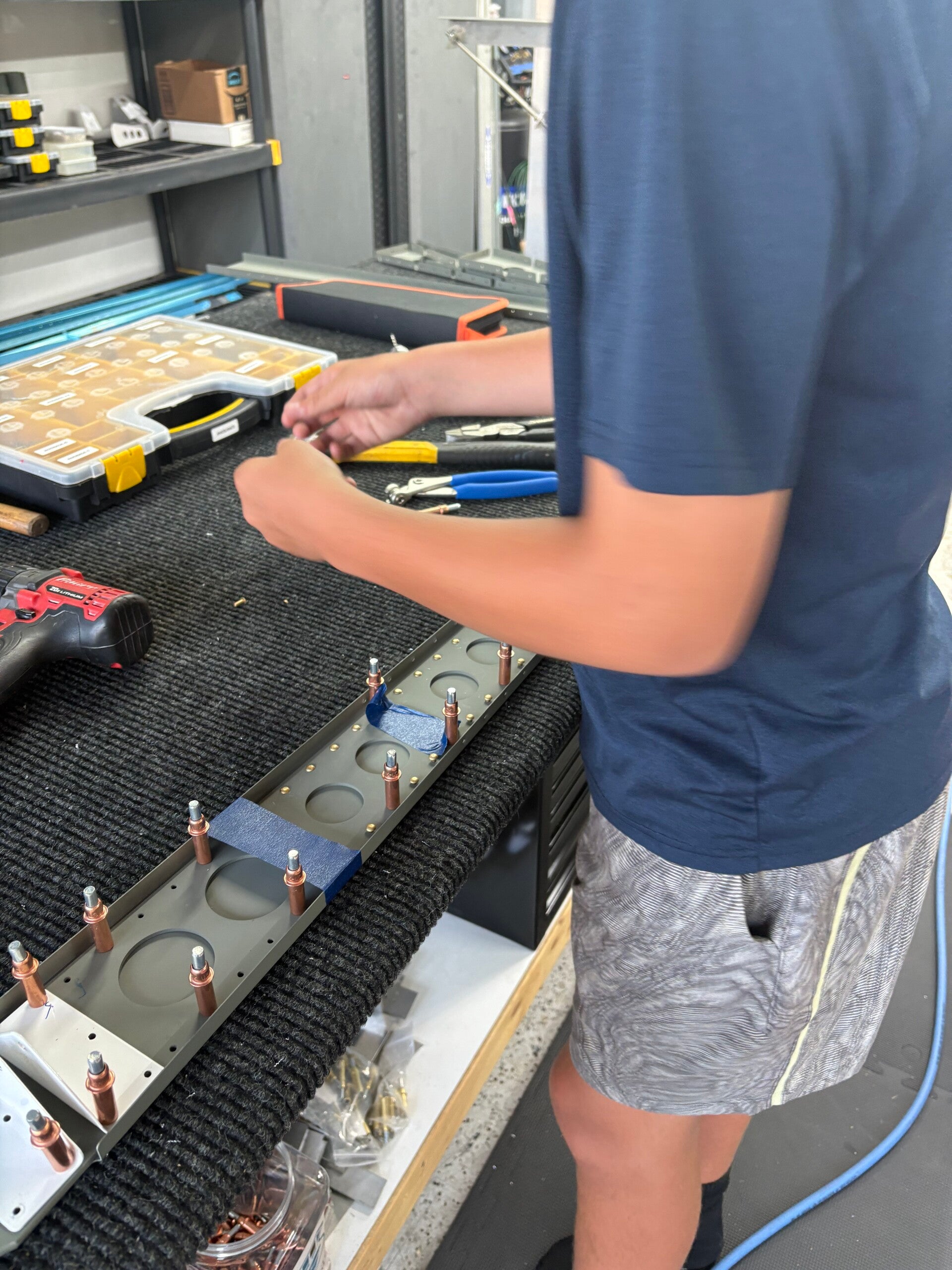
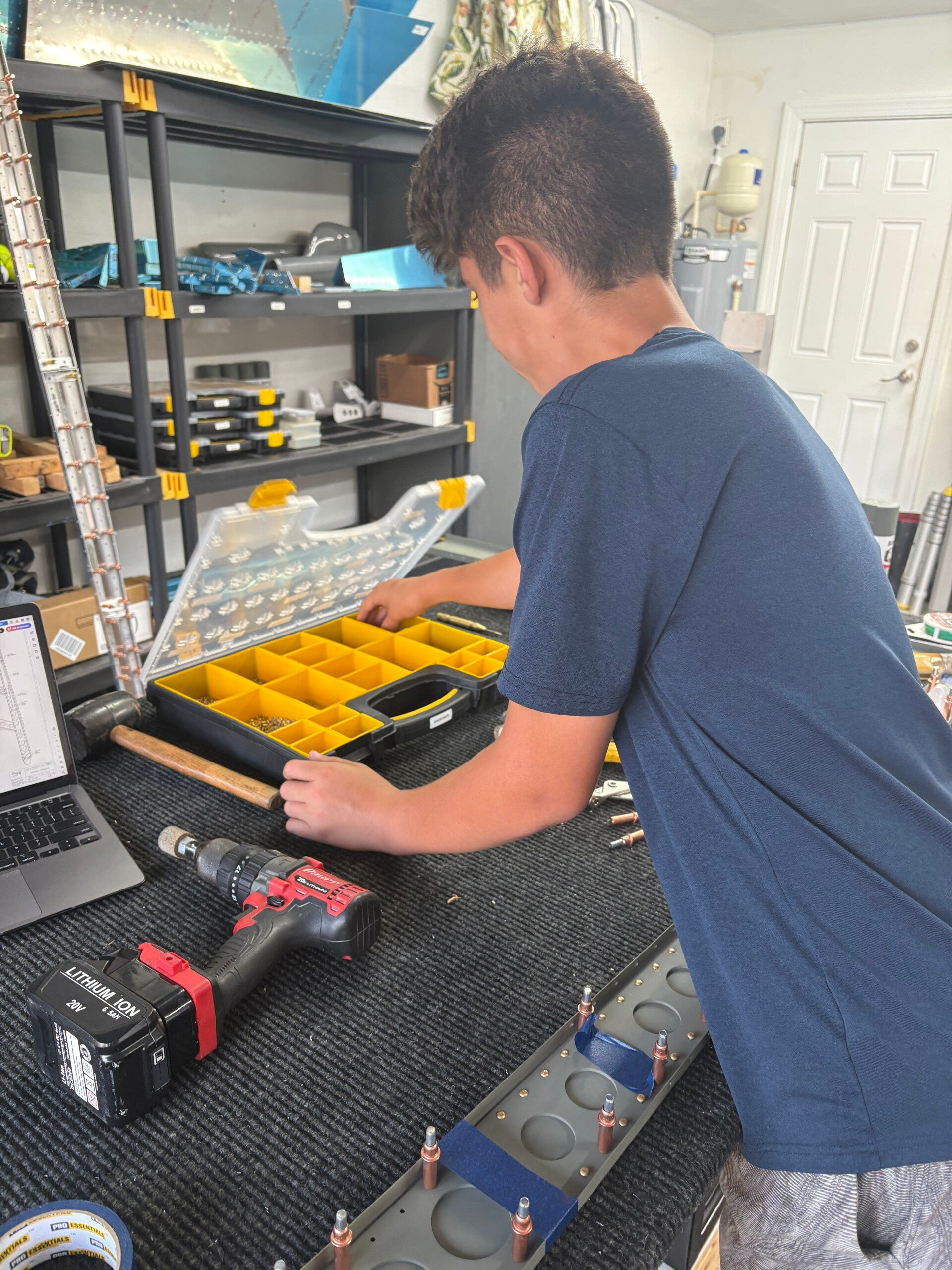
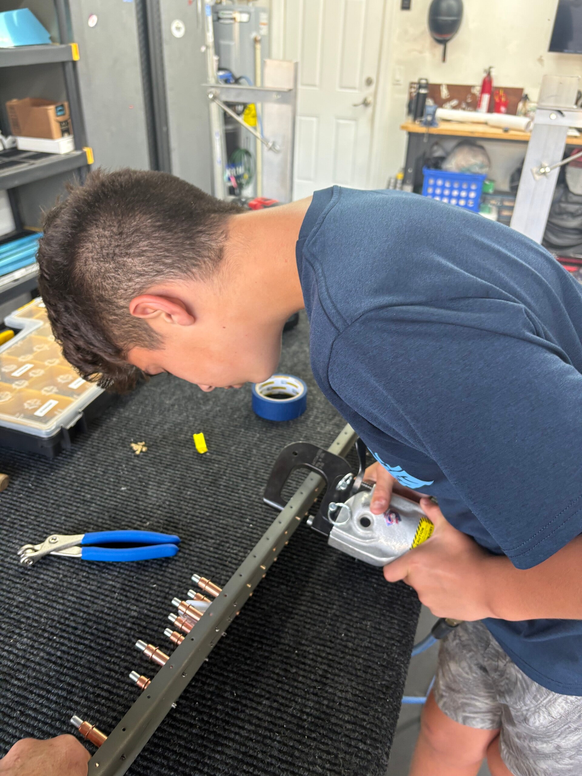
Drilled out a couple of mistakes and riveted as well.
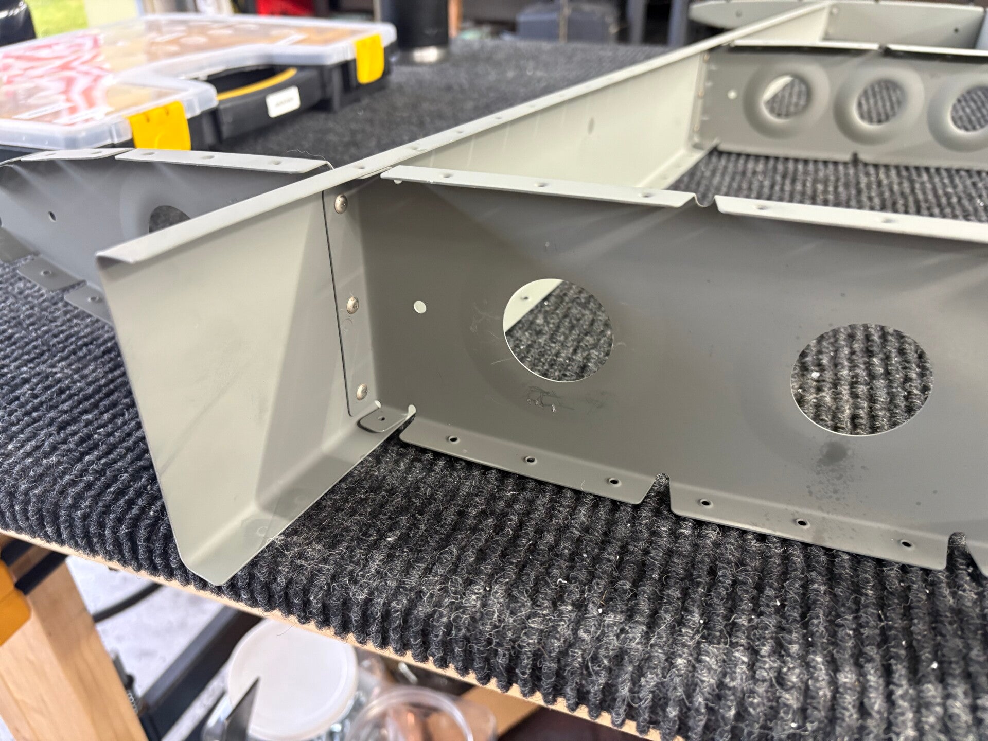
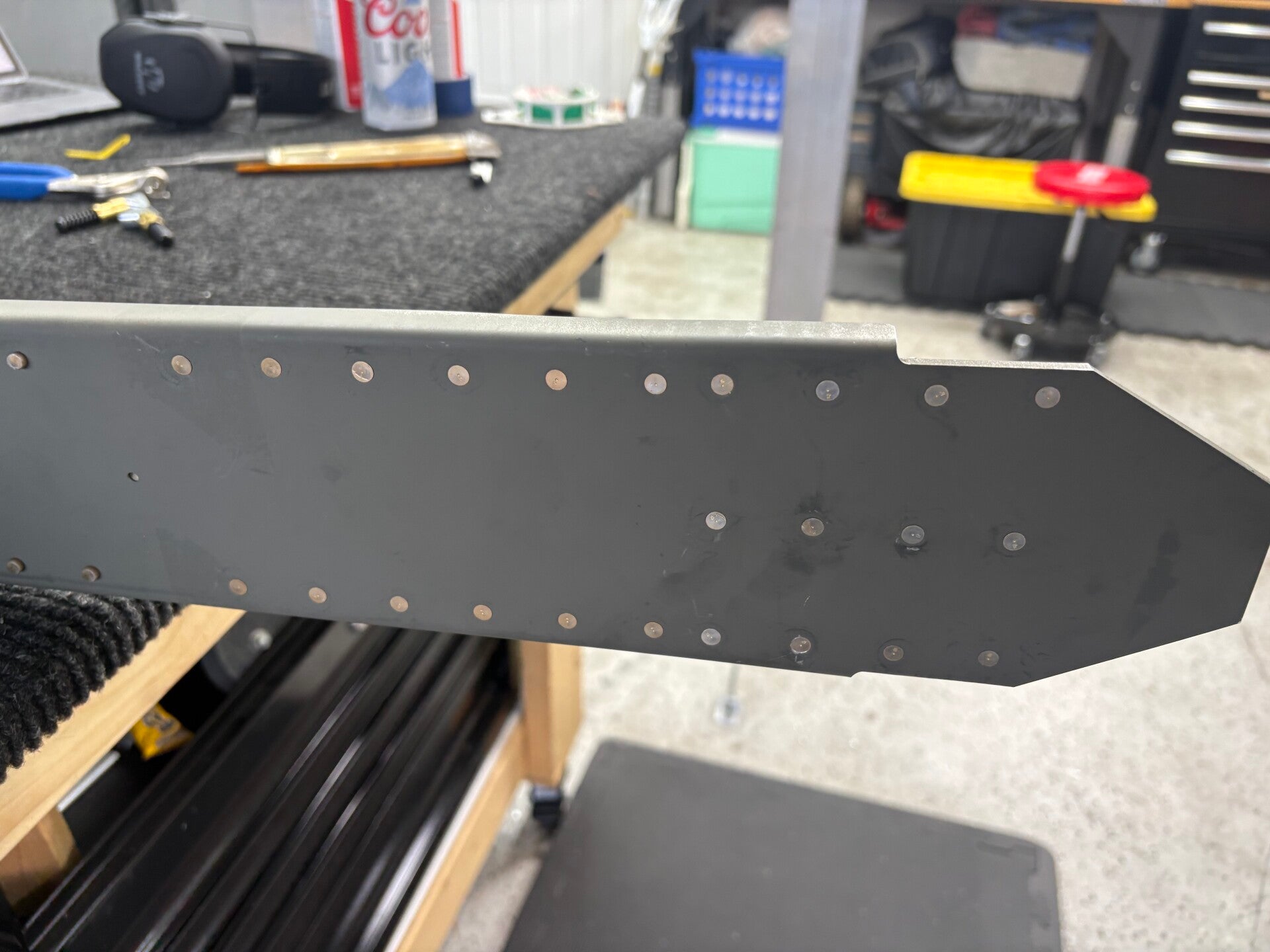
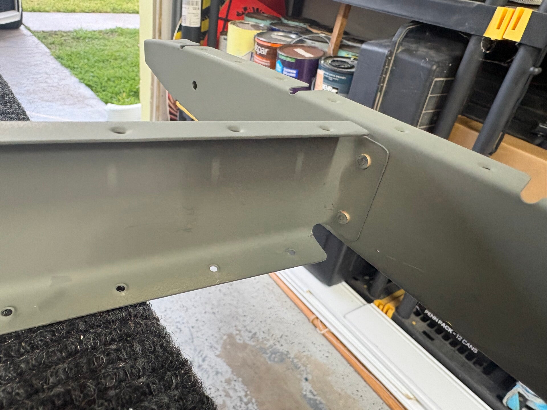
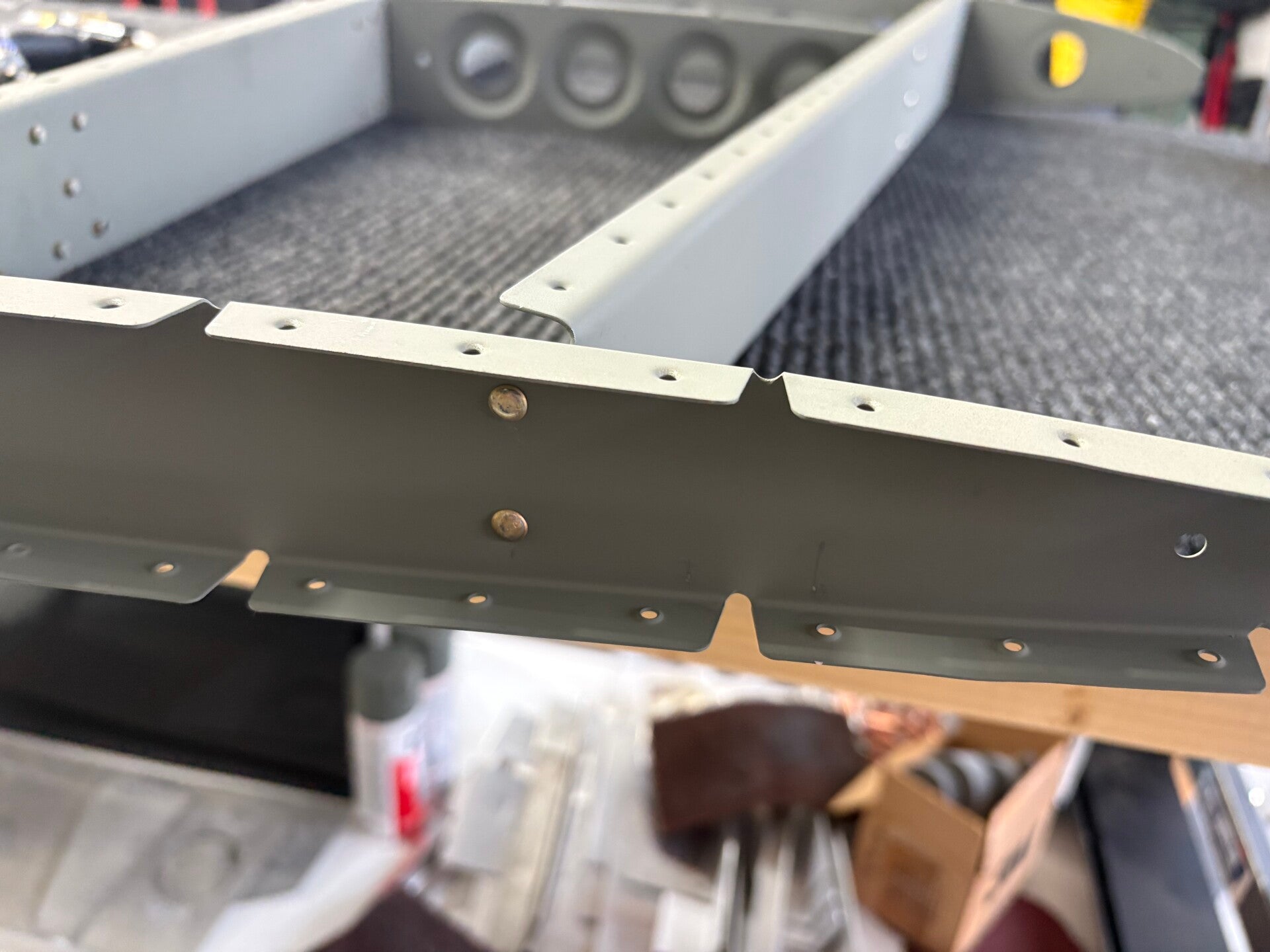
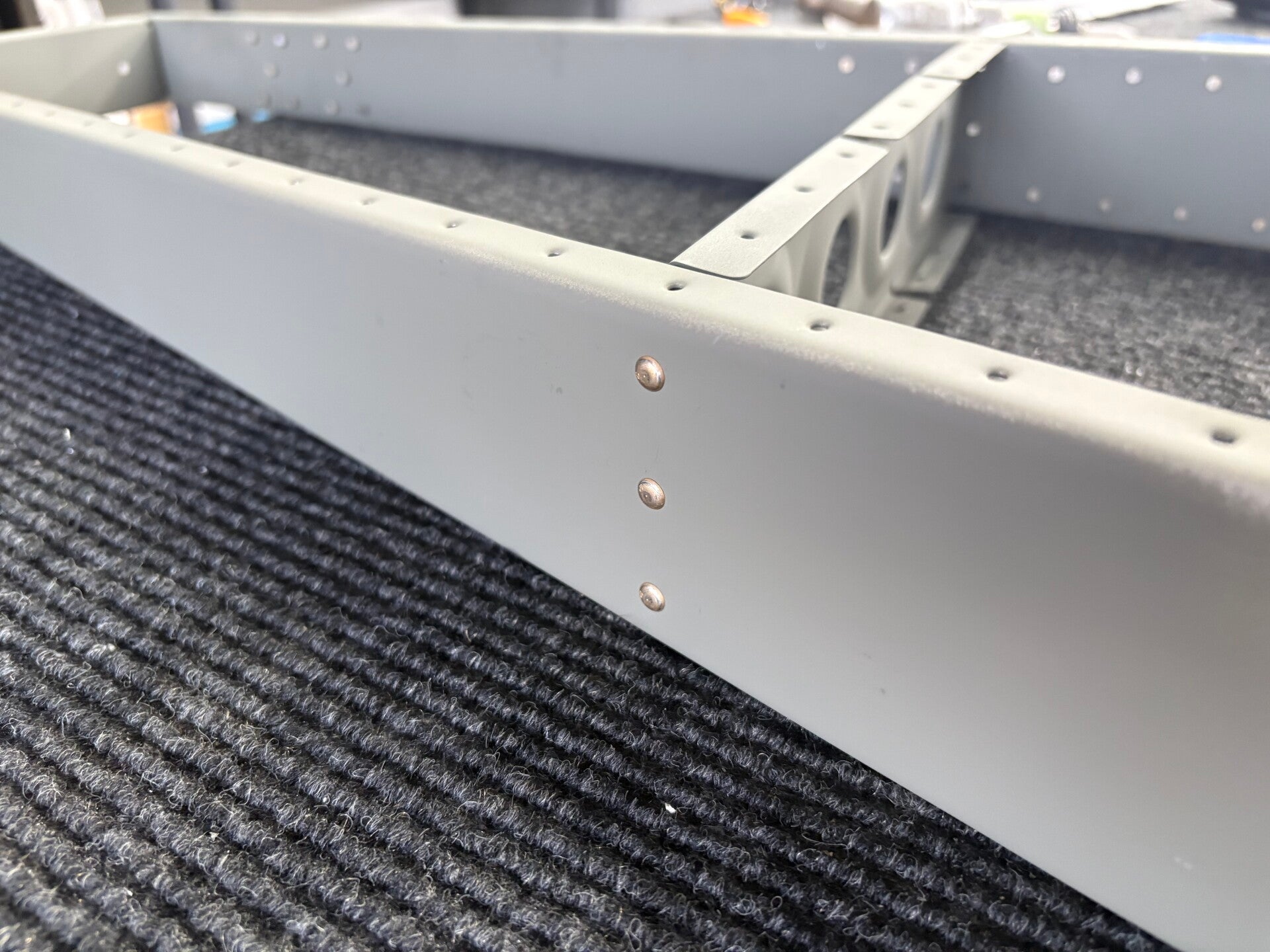
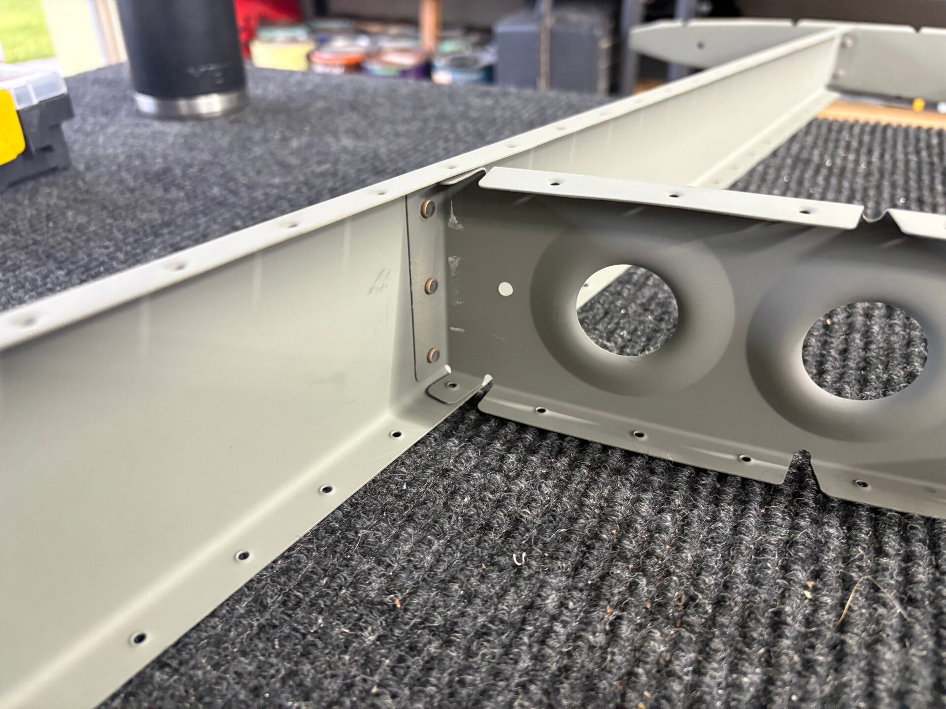
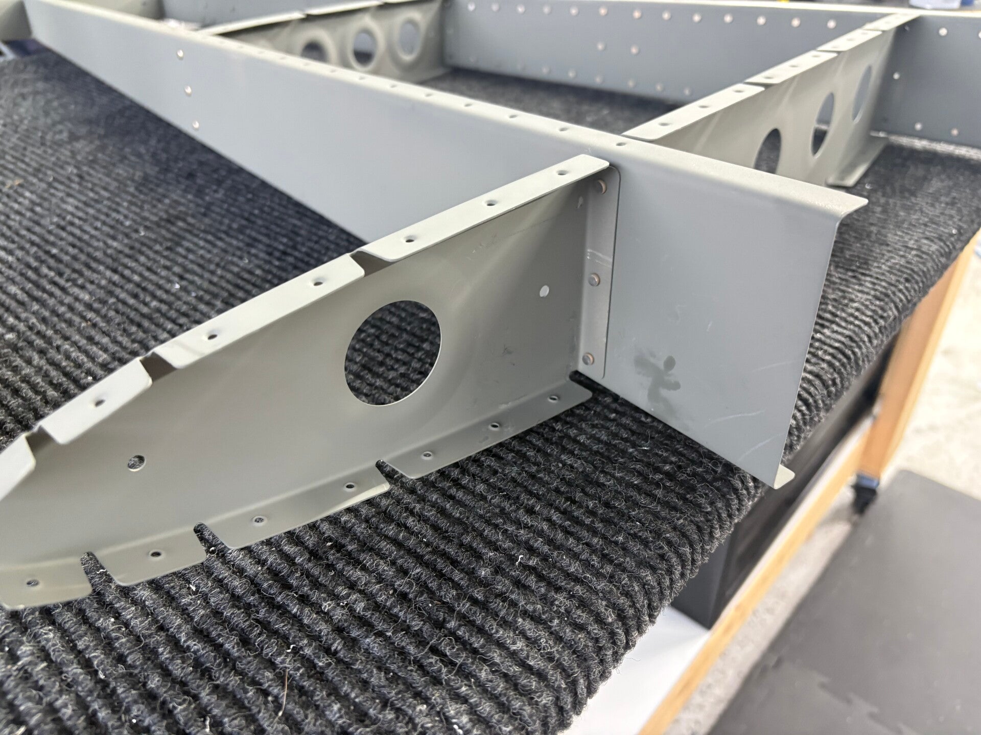
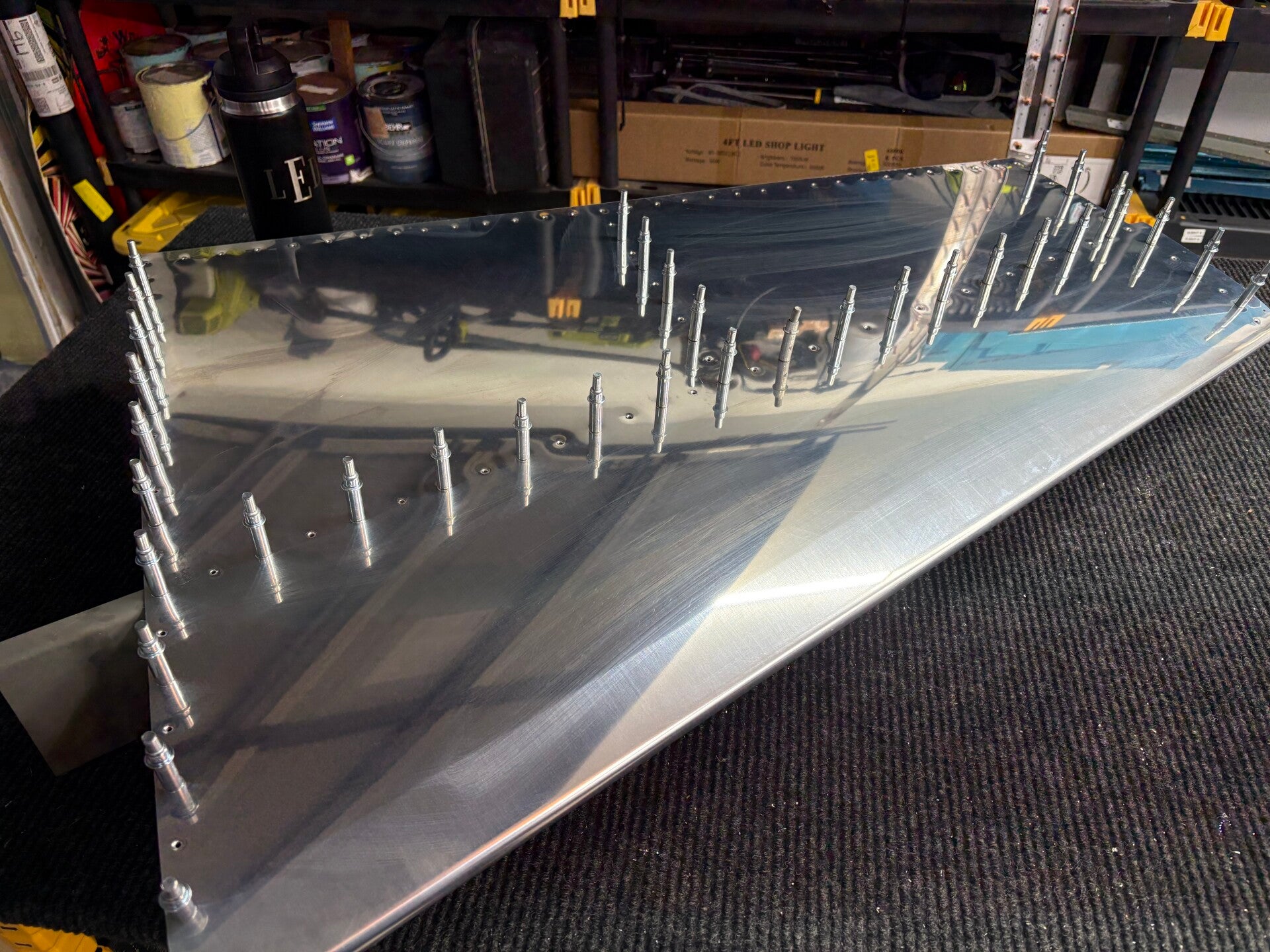
4/16/2026 (3 hours)
Manual section 6-5
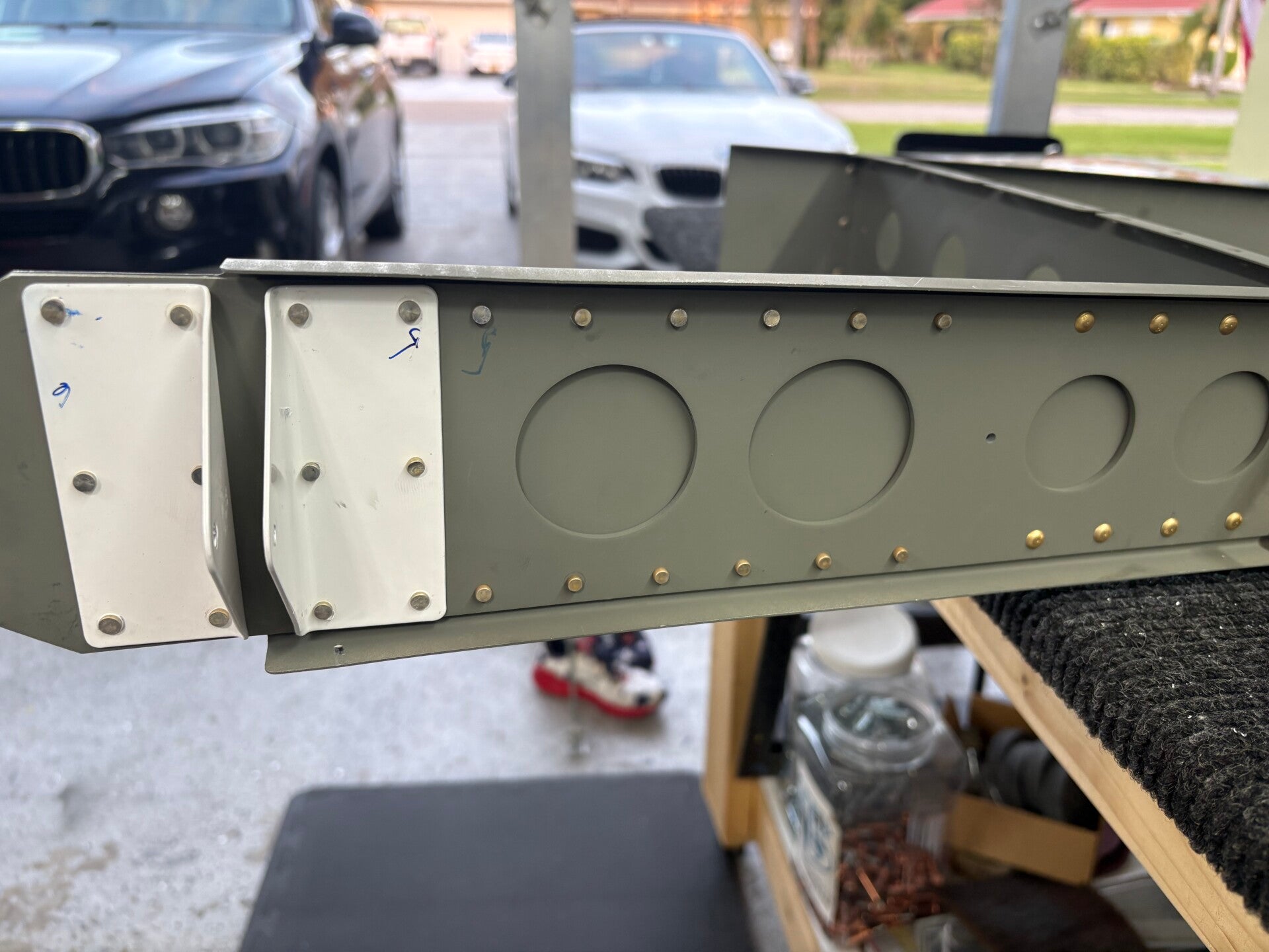
Steps 4-5. Riveted skin to skeleton and skin to spar. Also rear spar rivets.
Vertical Stabilizer is now complete!
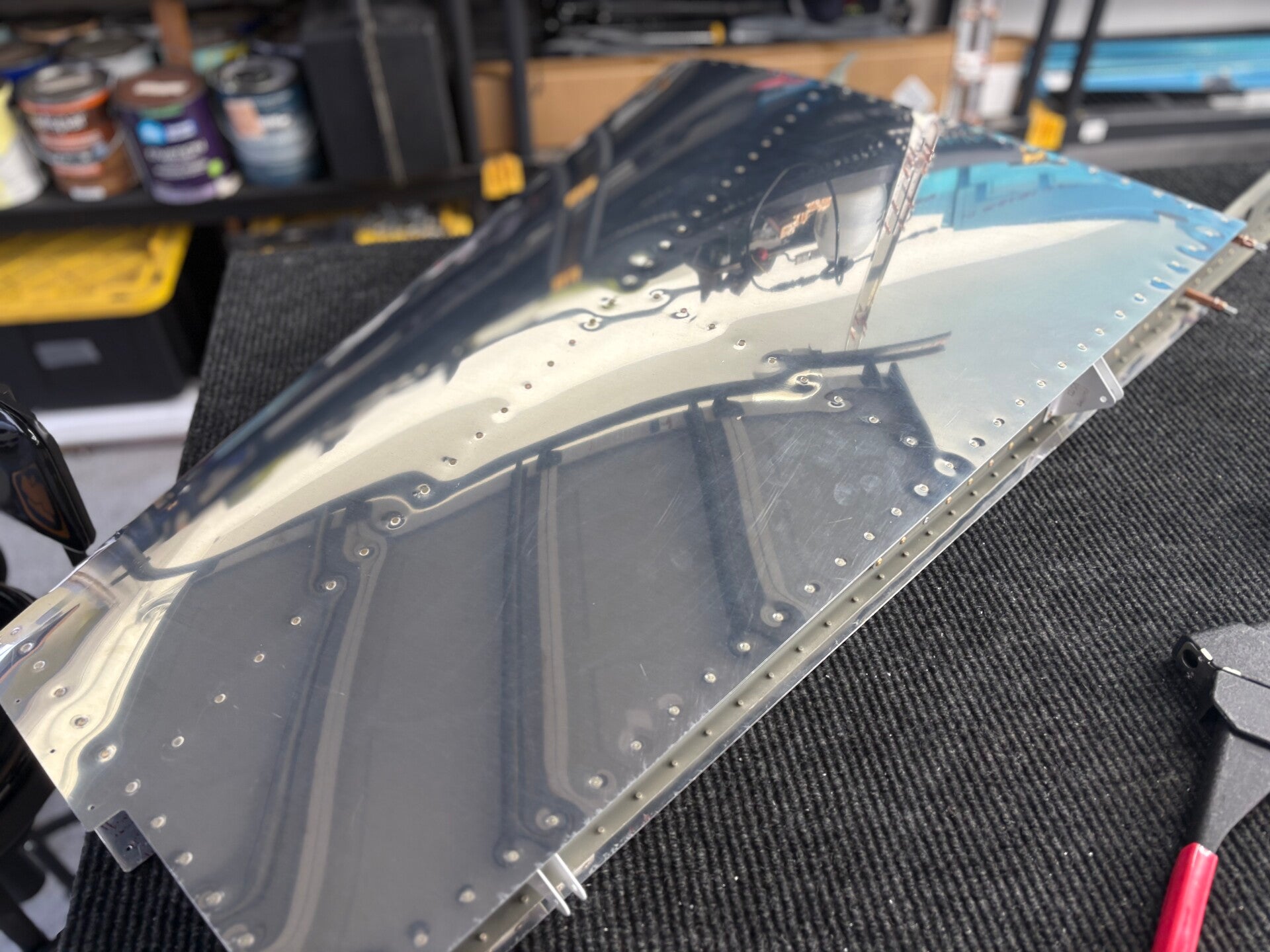
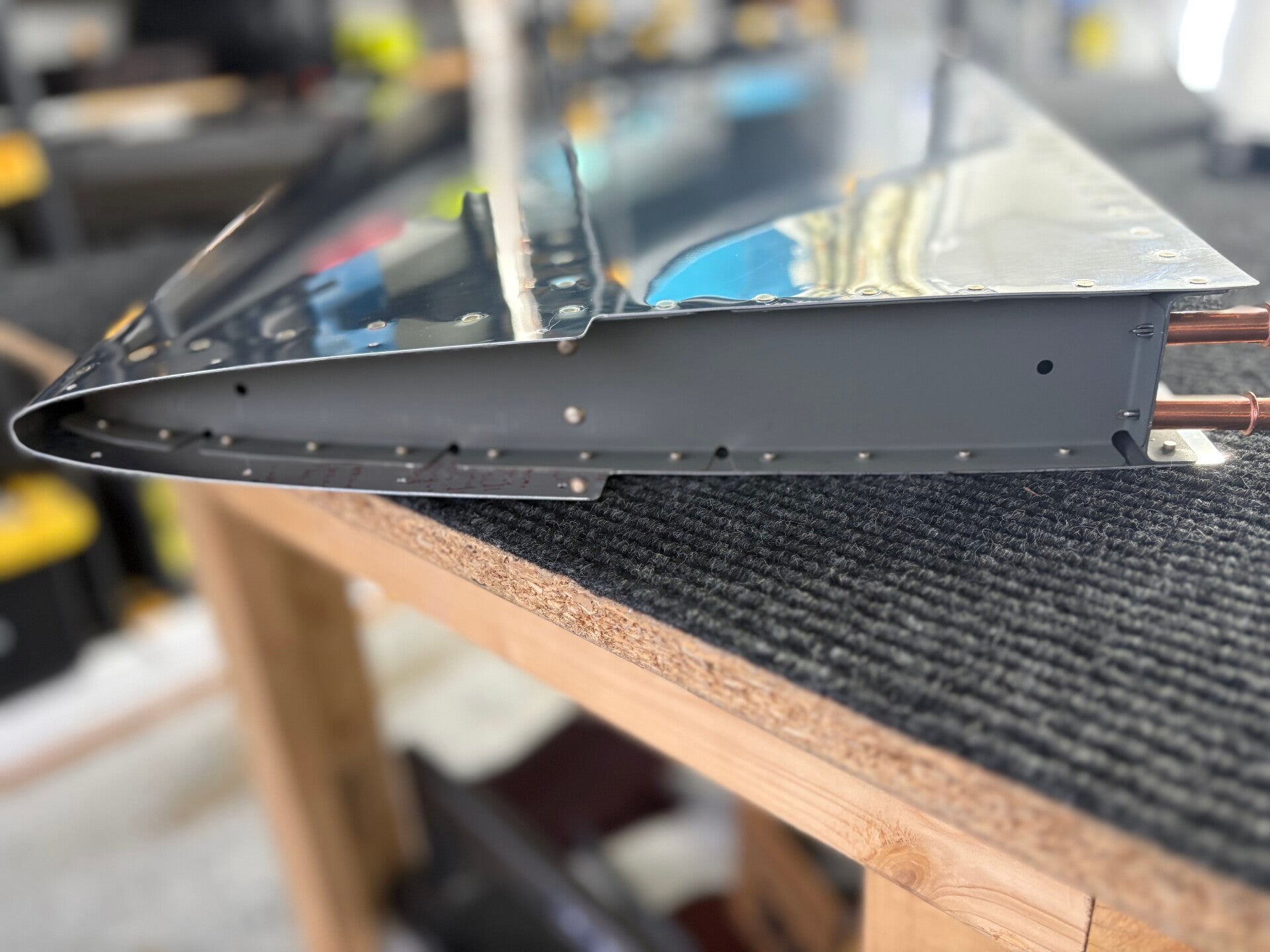
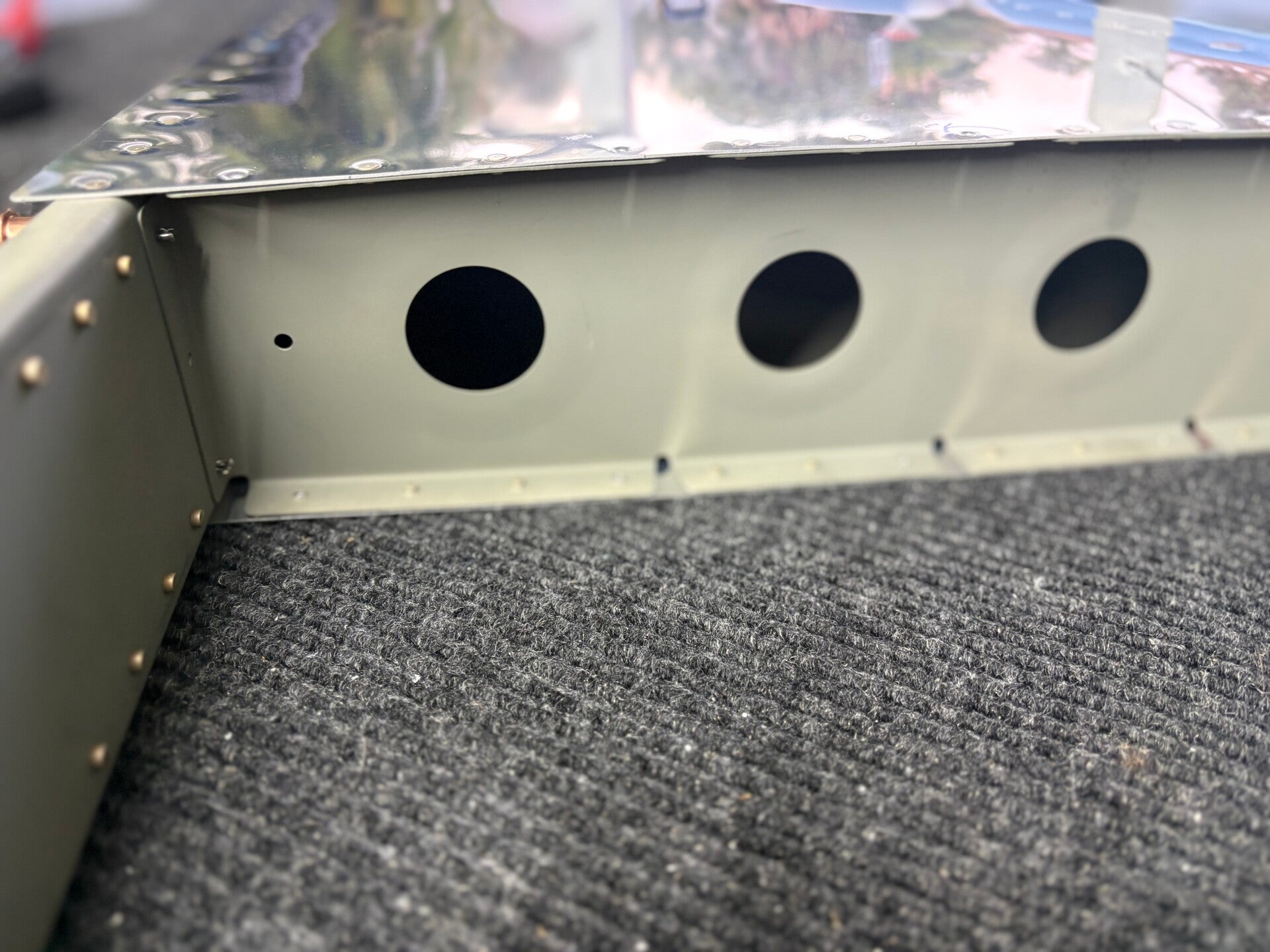
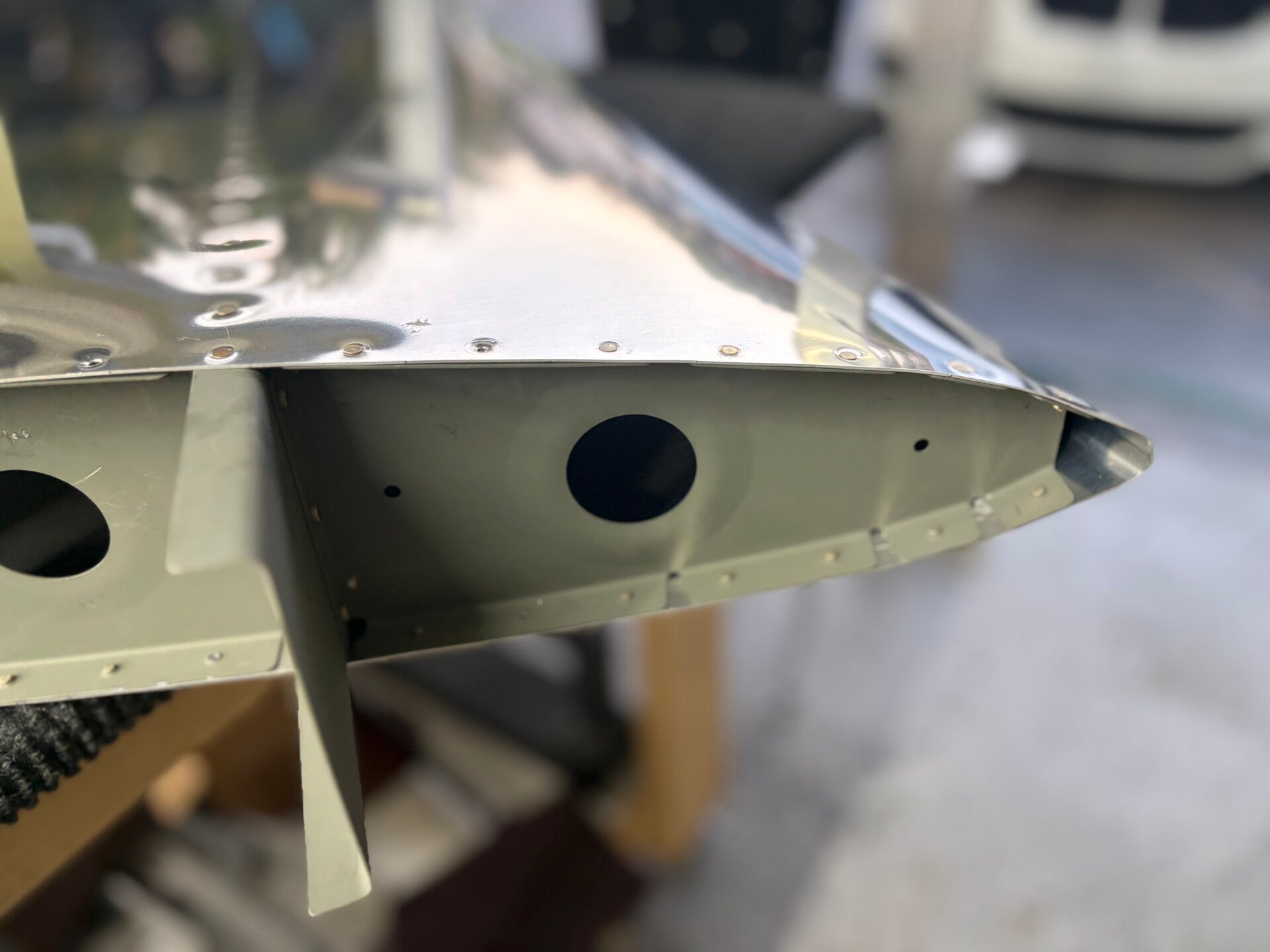
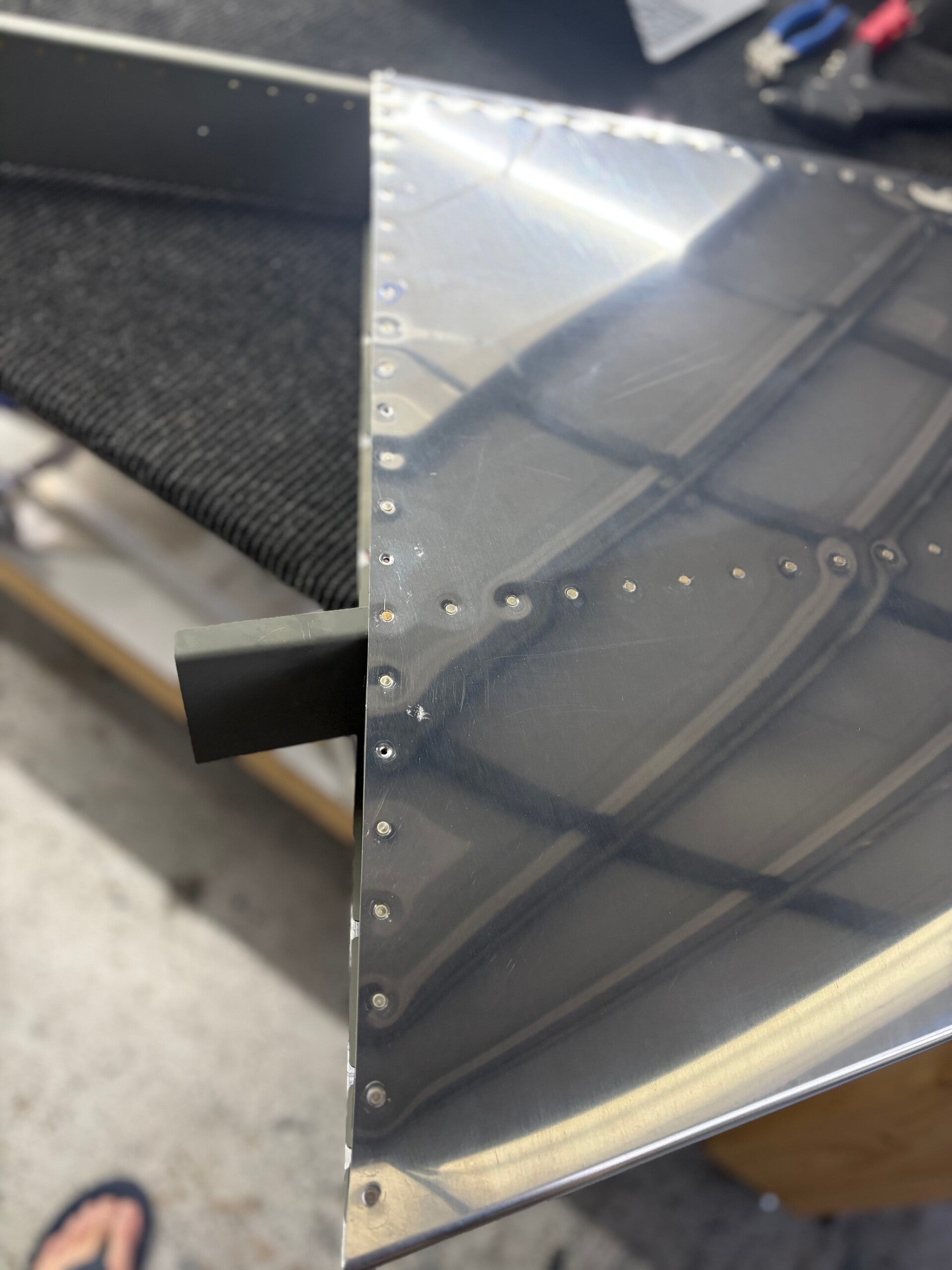
Rudder - COMPLETE
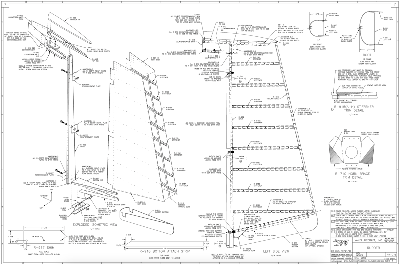
4/21/2026 (2 hours)
Manual Section 6-5
Steps 1-2.
Stiffener fabrication for right-side skin
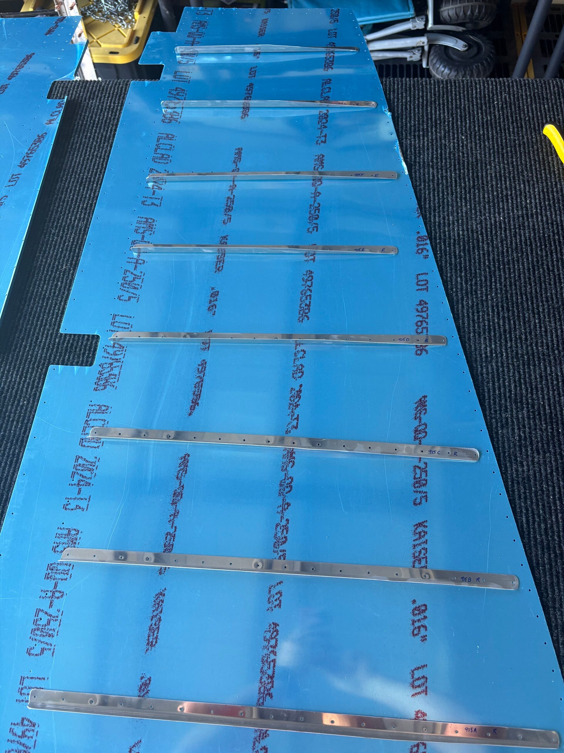
4/21/2026 (2 hours)
Manual Section 6-5
Steps 1-2. Stiffener fabrication for left-side skin. Cleco all on. No pics.
4/21/2026 (4 hours)
Manual Section 6-5
Steps 3-8.
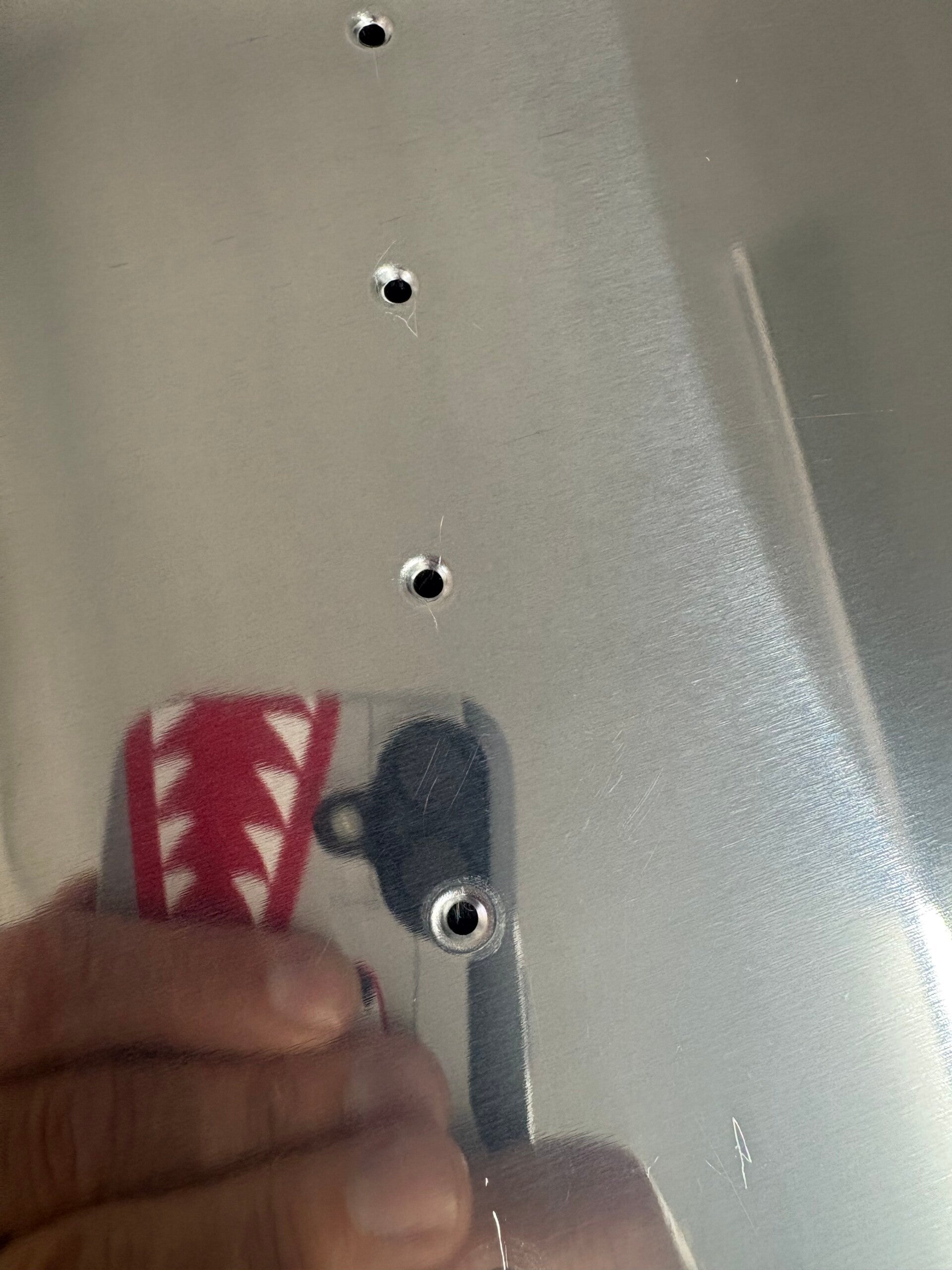
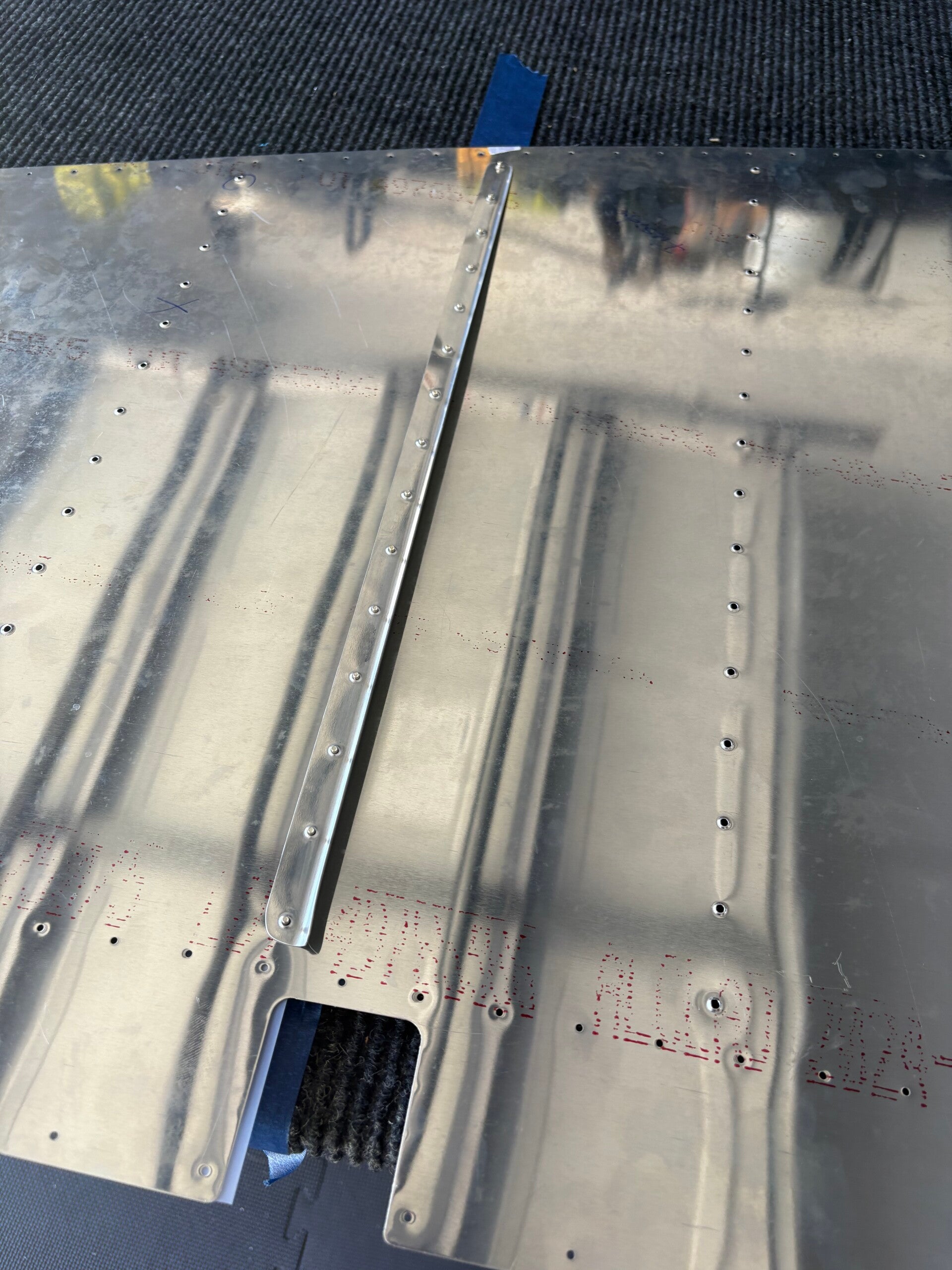
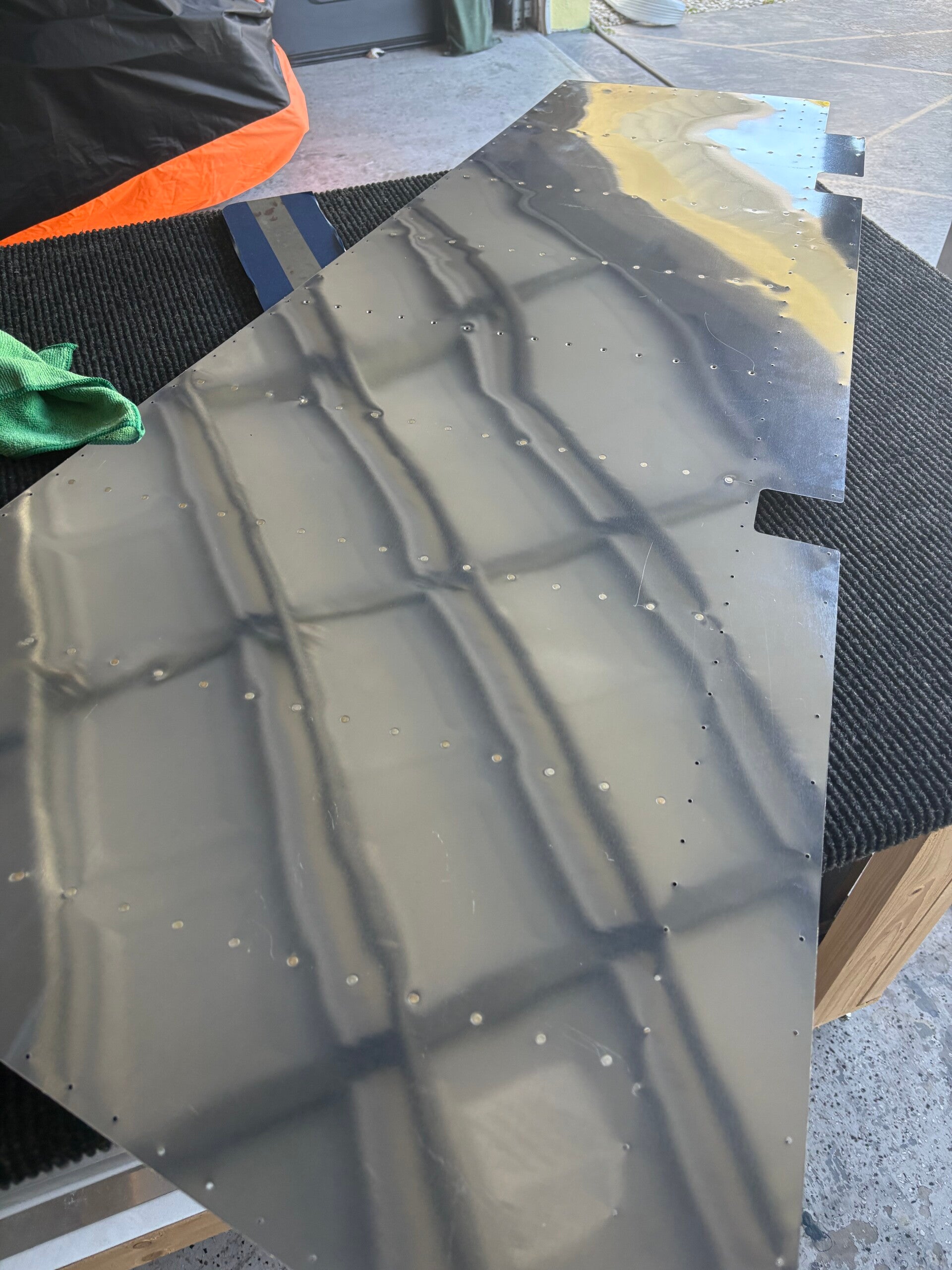
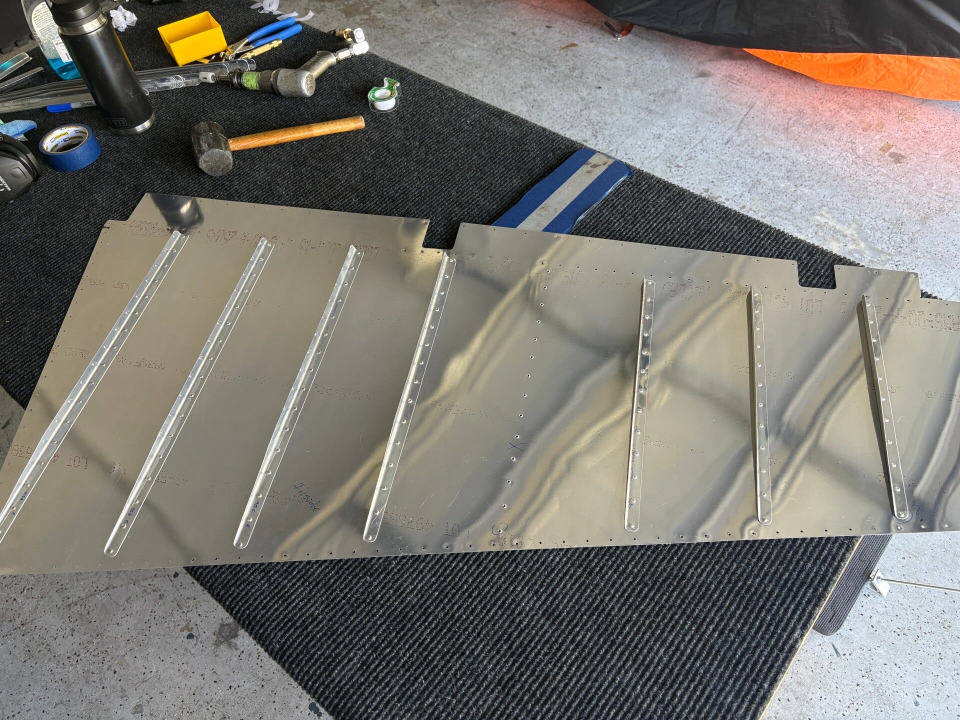
Cleco all stiffies on. Drill, debur and then dimple all. Started back-riveting. Left skin good to go except one stiffy. Started right side and screwed up. I was back-riveting and started on a rivet that was at the edge of the backplate. So, ordered a new skin and stiffies. Costly mistake.
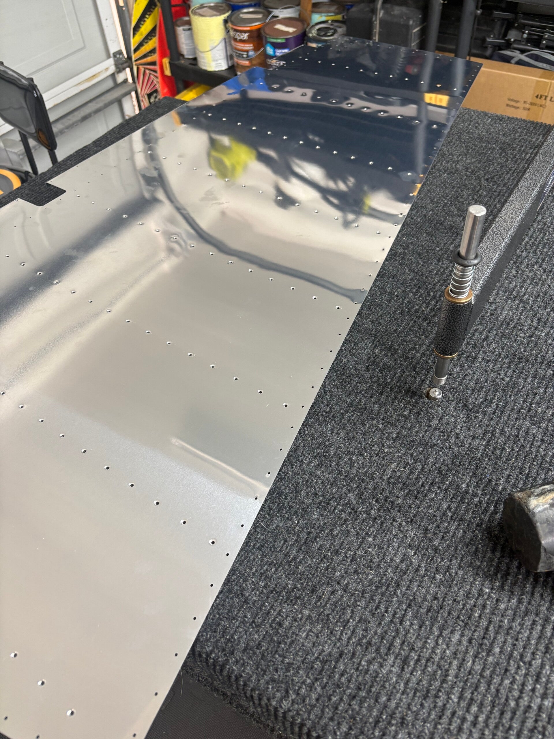
4/21/2026 (1 hours)
Manual Section 6-6
Steps 1-6.
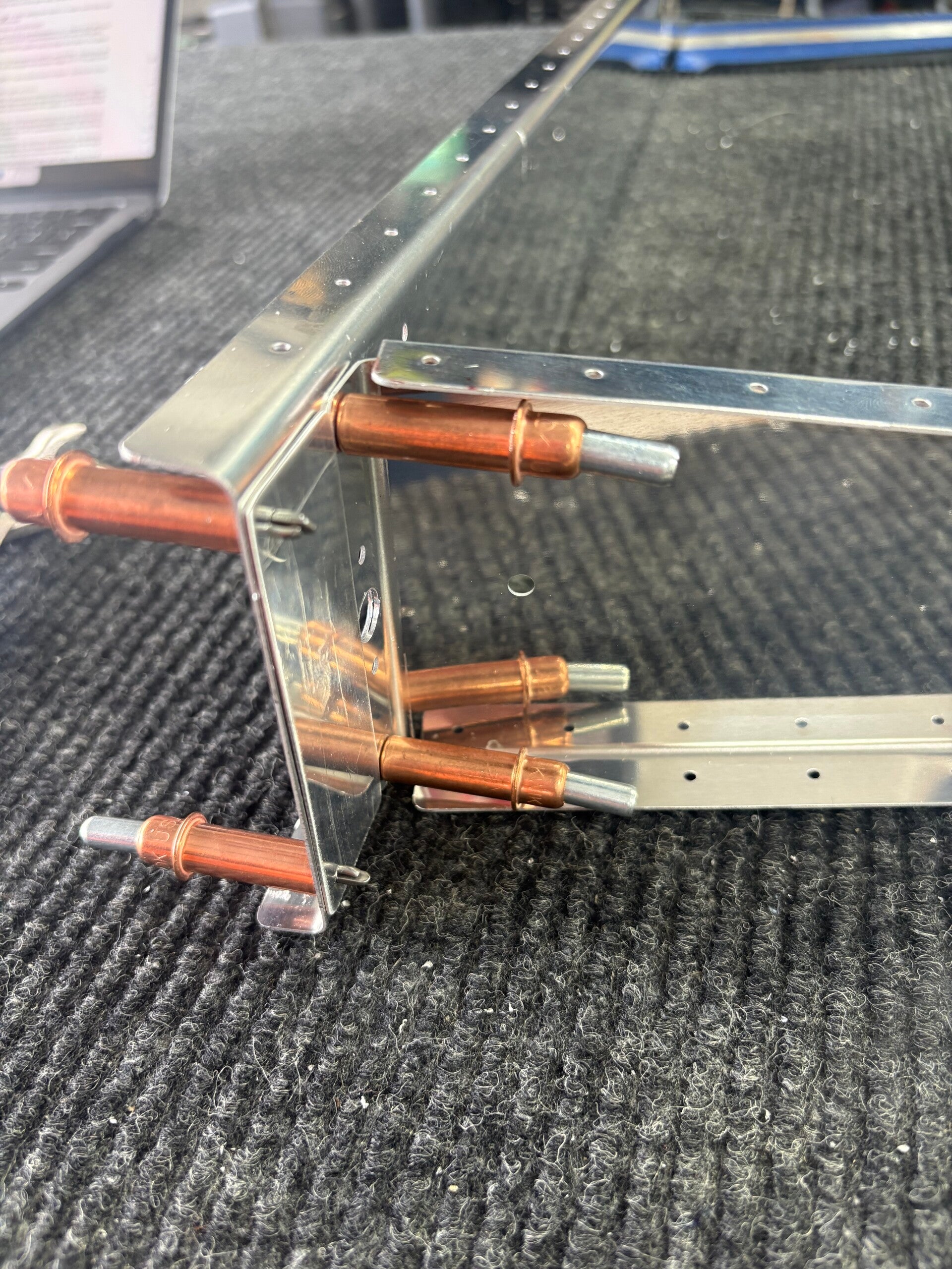
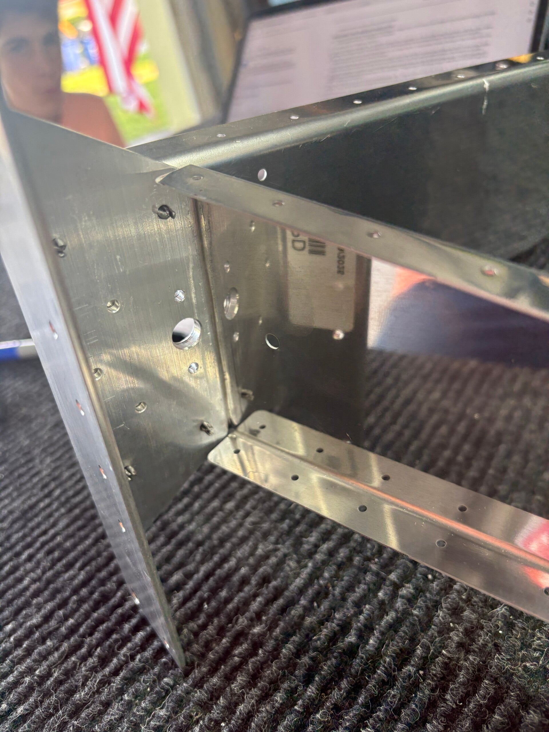
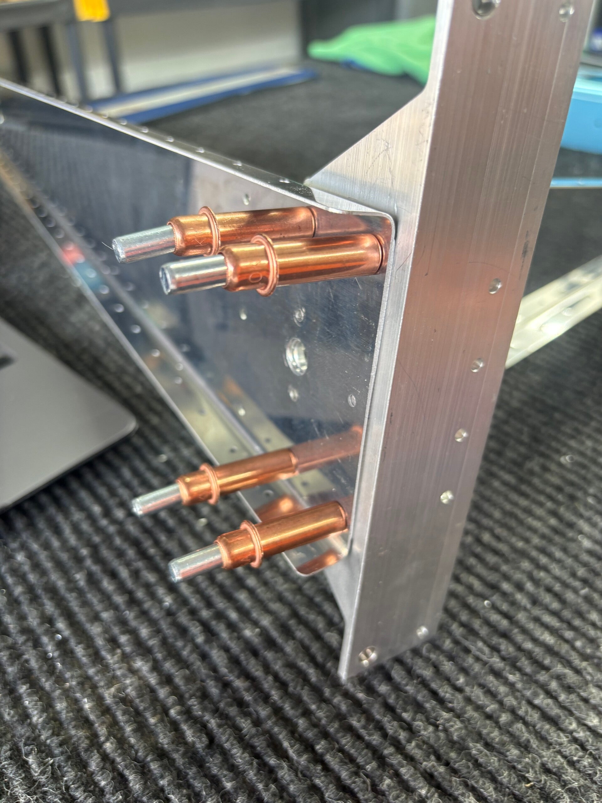
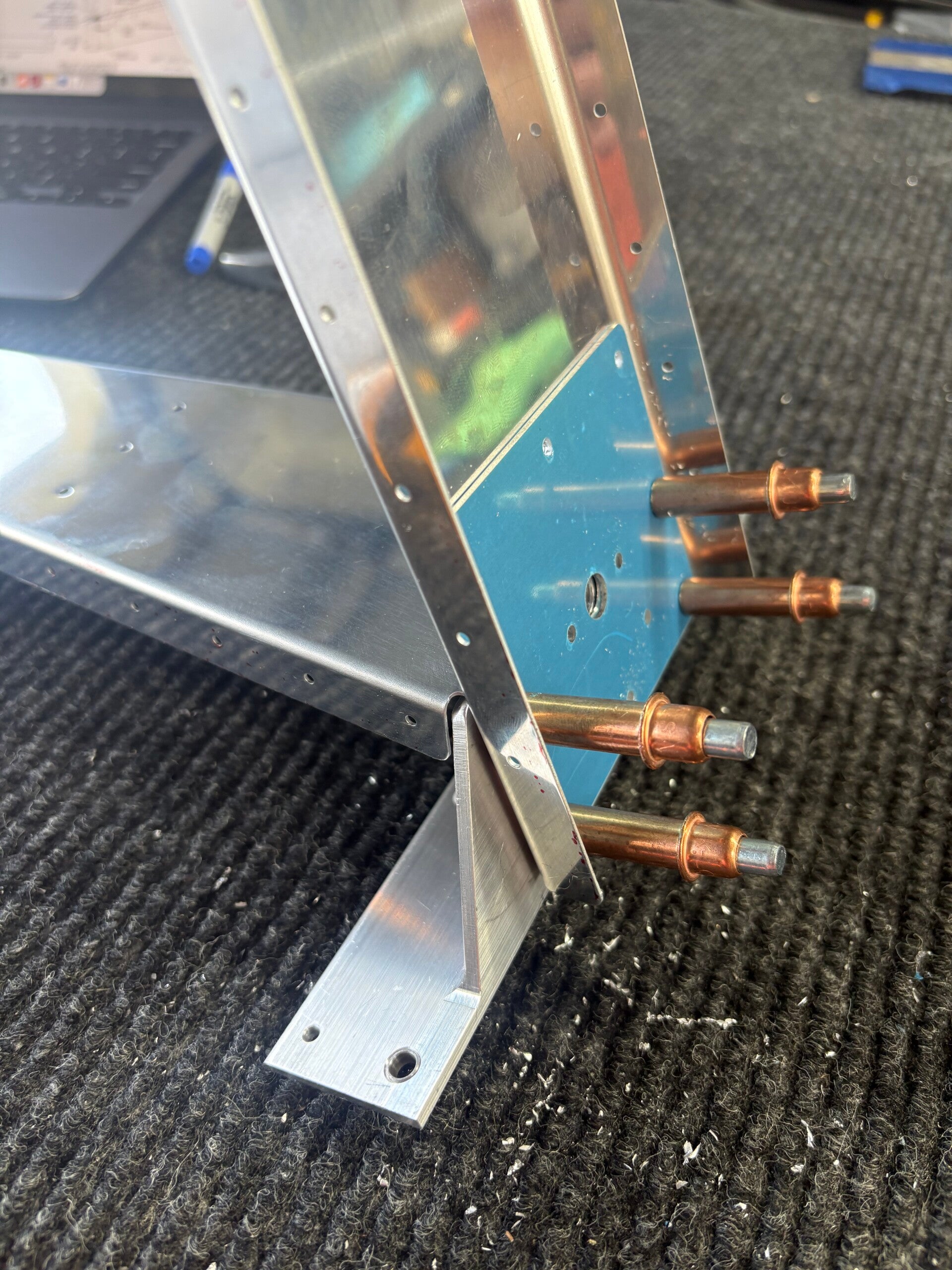
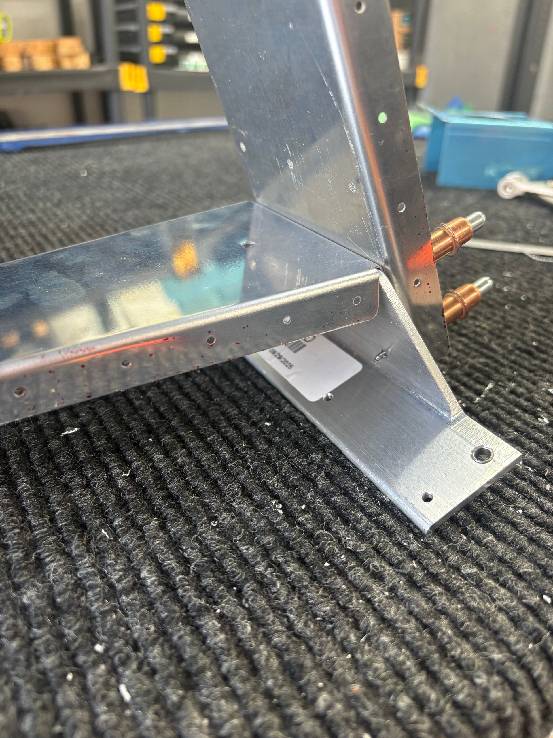
Fabricated shim. Assembled spar, bottom rib, horn (trimmed to fit bottom rib), shim and front side reinforcement plate. Match drilled to #30.
4/21/2026 (1 hours)
Manual Section 6-6
Steps 6-7.
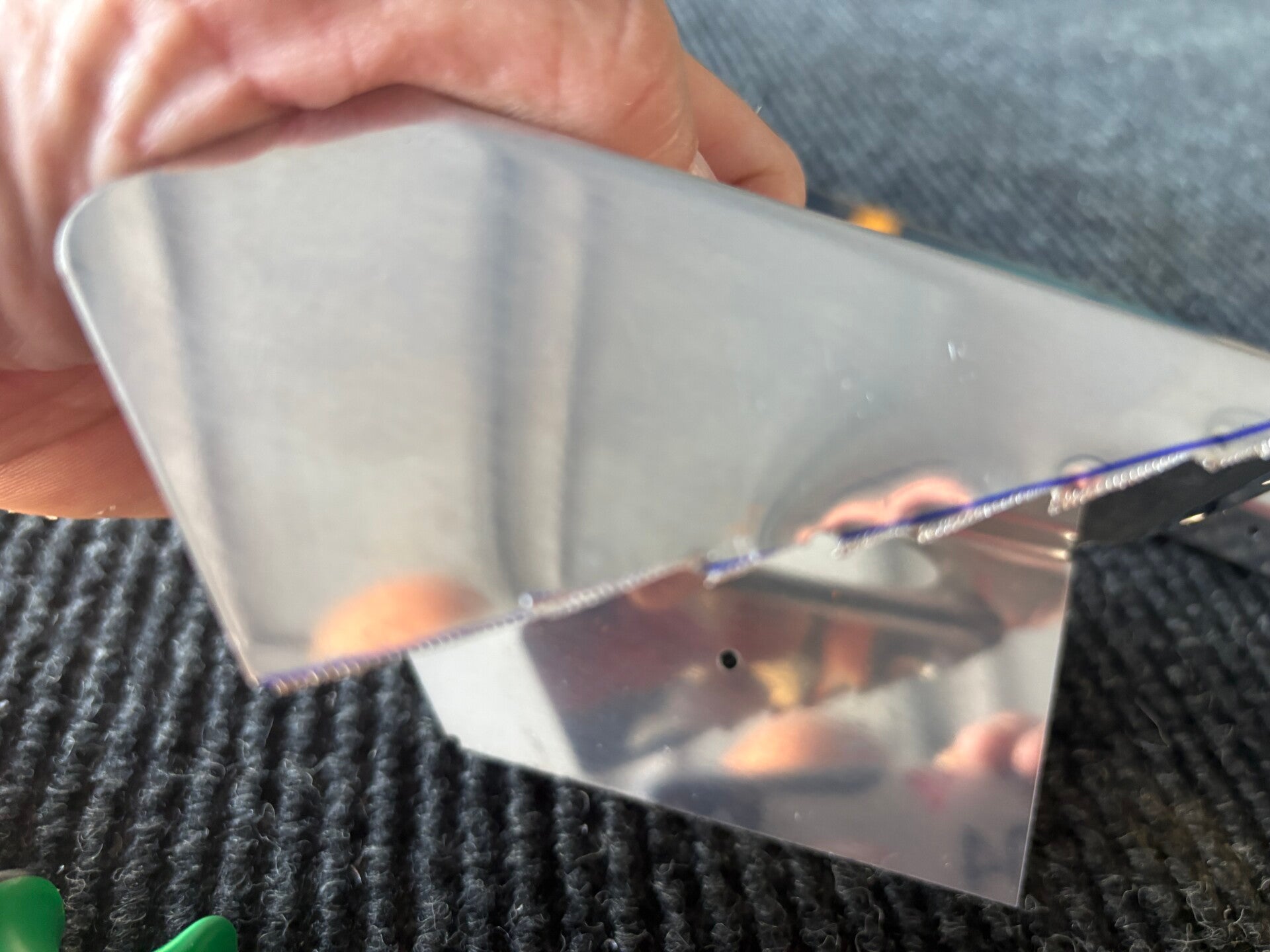
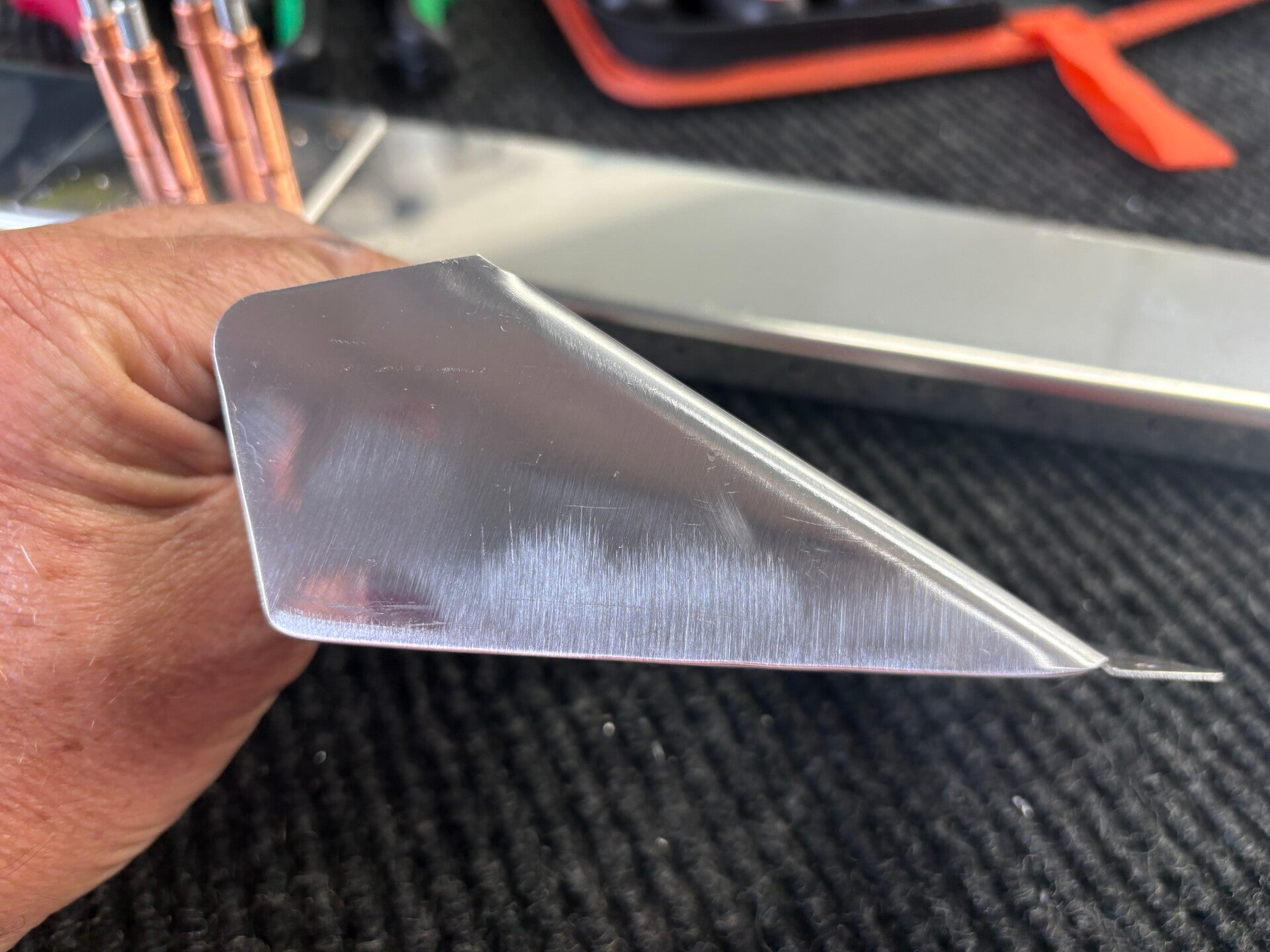
Added reinforcement plates and top two ribs. Then match drilled to #30. Trimmed R-710 per drawing. Now on hold because missing R-913. Van's sent the incorrect part in the kit. They sent 713 which is for another airplane ... not the 7. So, that makes 2 sections on hold - Rudder and HS!
5/11/2026 (1 hours)
Manual Section 6-5
Steps 3-8
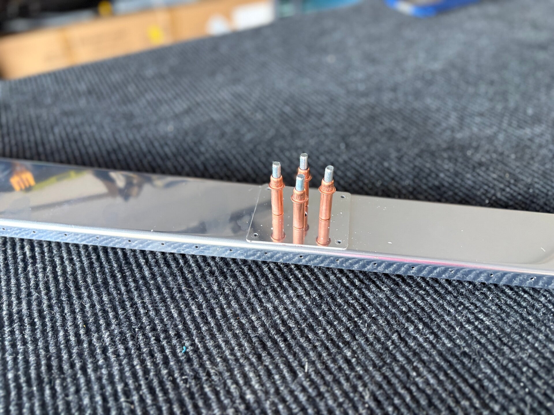
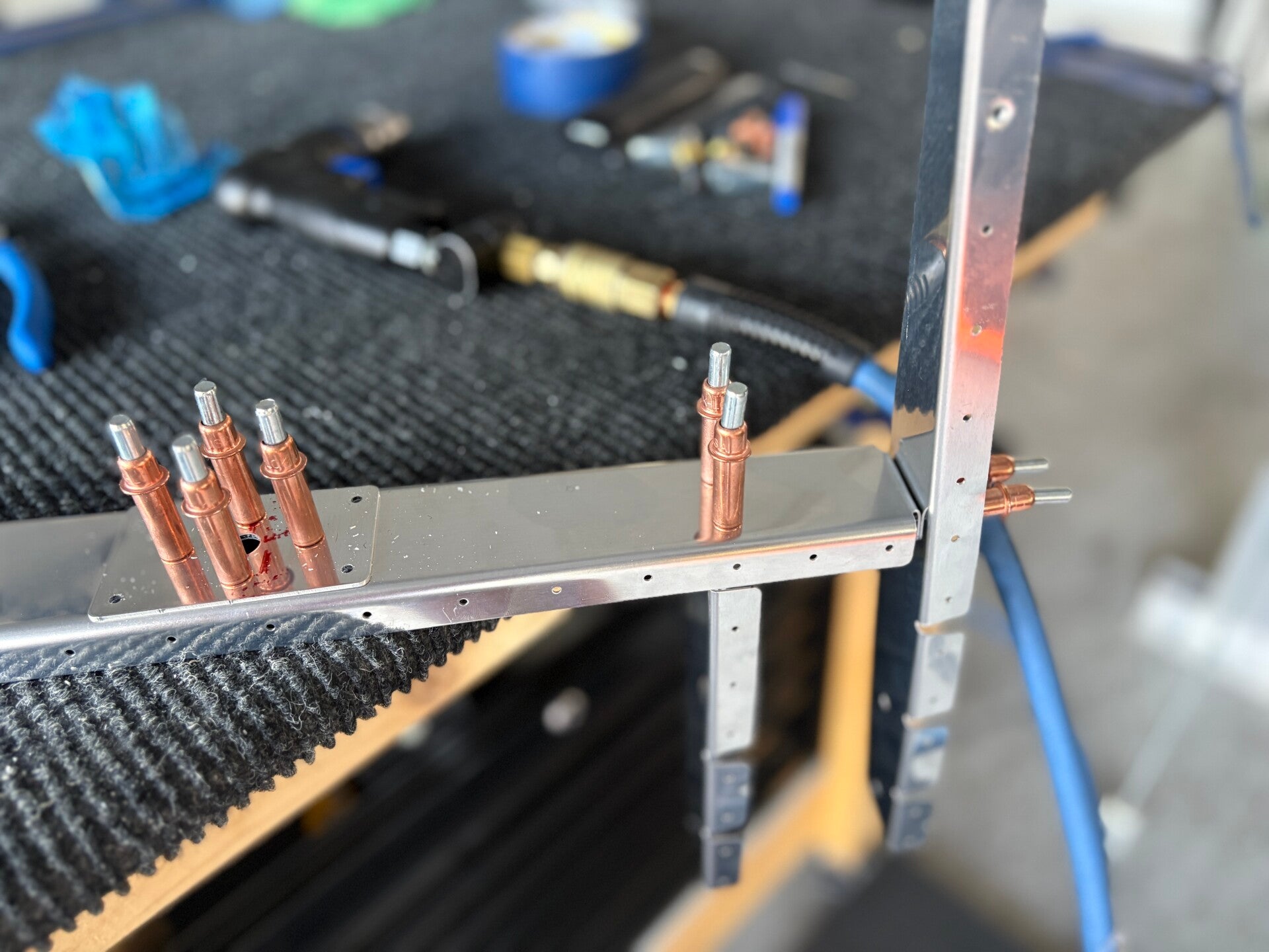
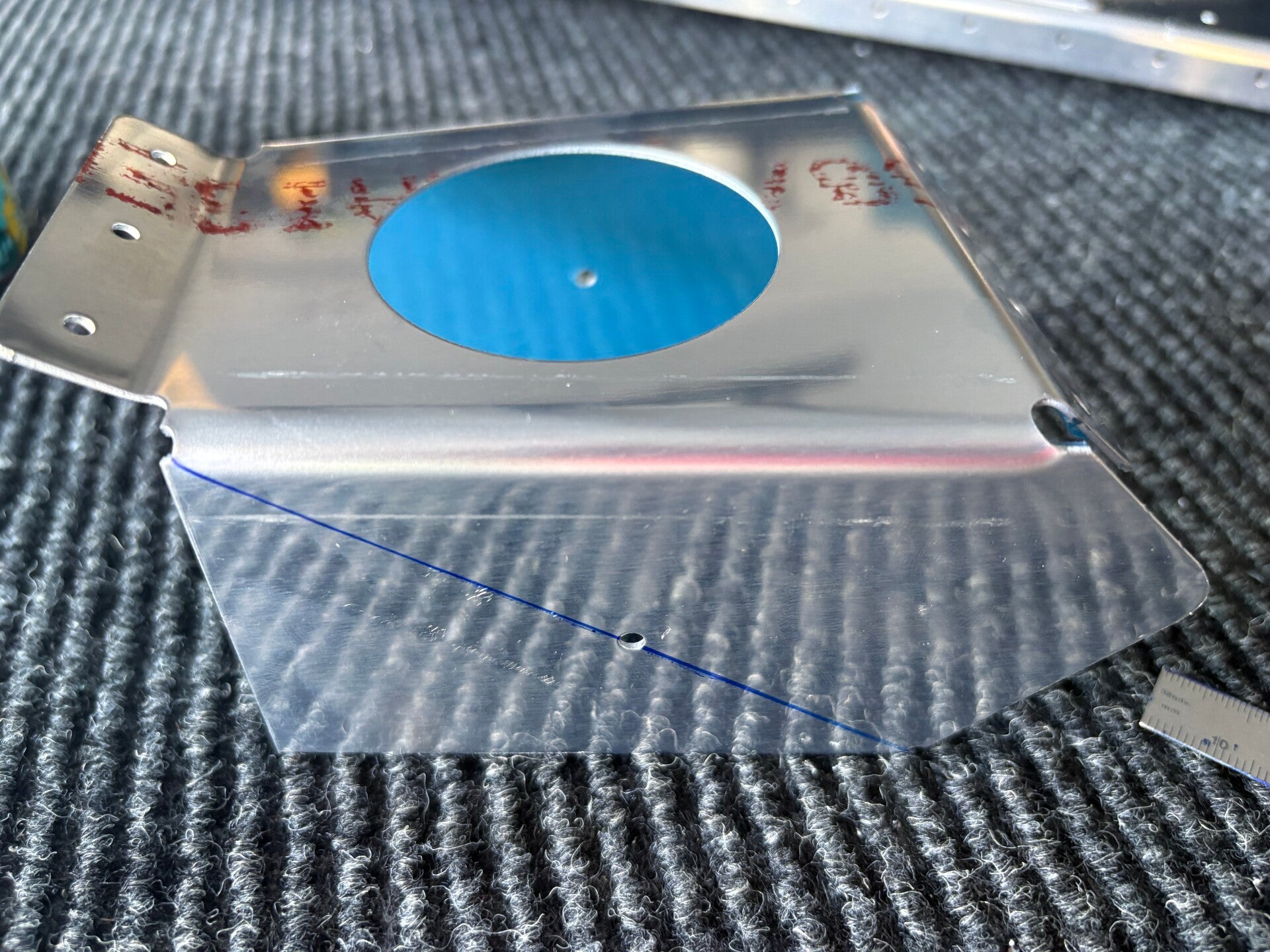
I received my oops stiffy finally last week while I was away for work. Took the time to cut, drill, prime and rivet it.
5/13/2026 (1 hours)
Manual Section 6-5
Steps 9
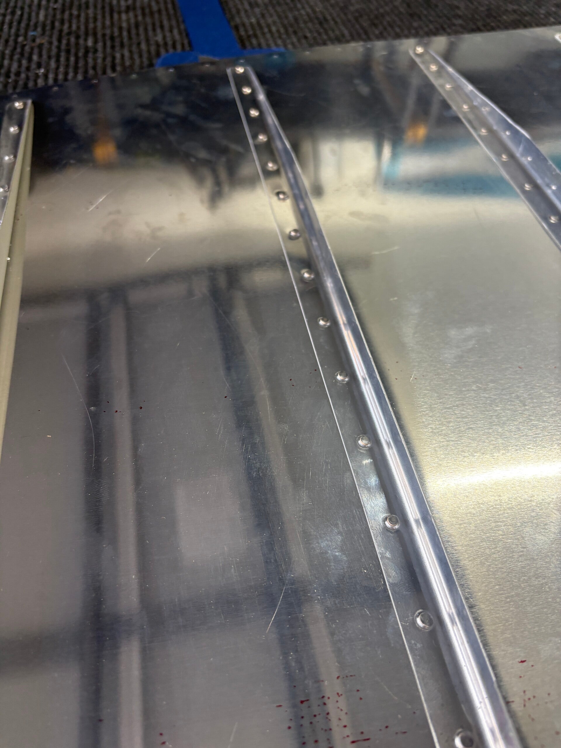
I received the missing counterbalance skin from Van's. Clecoed it in and and drilled to #40.
6/15/2026 (1 hours)
Manual Section 6-5
Steps 4
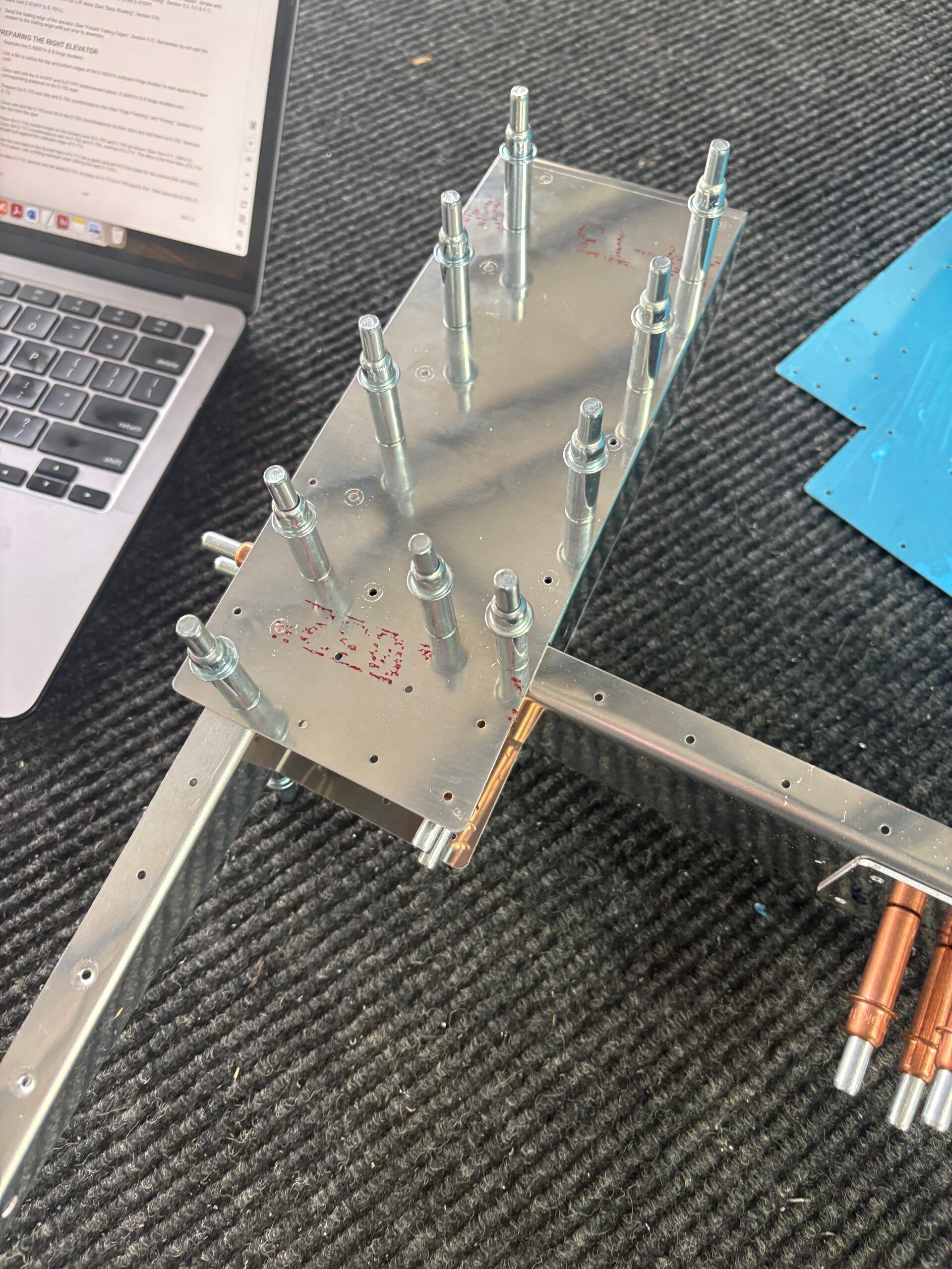
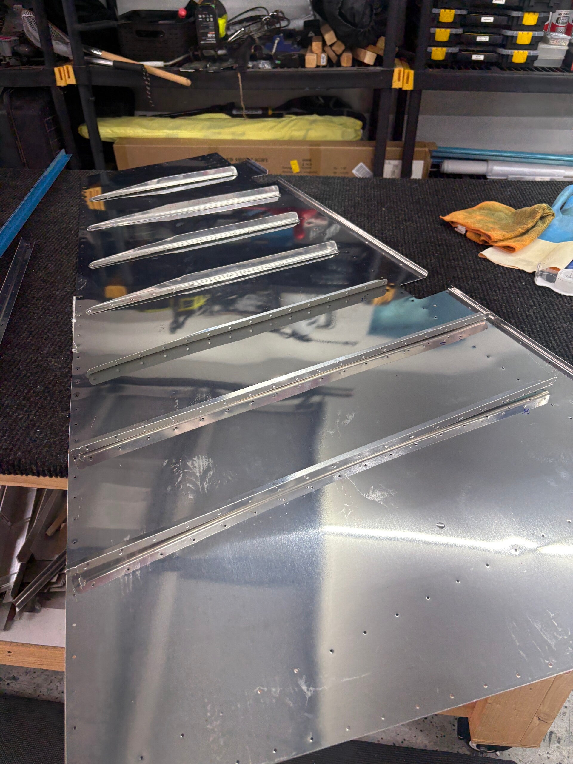
The new left skin finally arrived a few weeks back. I managed to get some time on it tonight. Just getting my bearings with the stiffeners I already made and what I have left to do. Identified the cuts to be made.
6/16/2026 (1 hours)
Manual Section 6-5
Steps 4
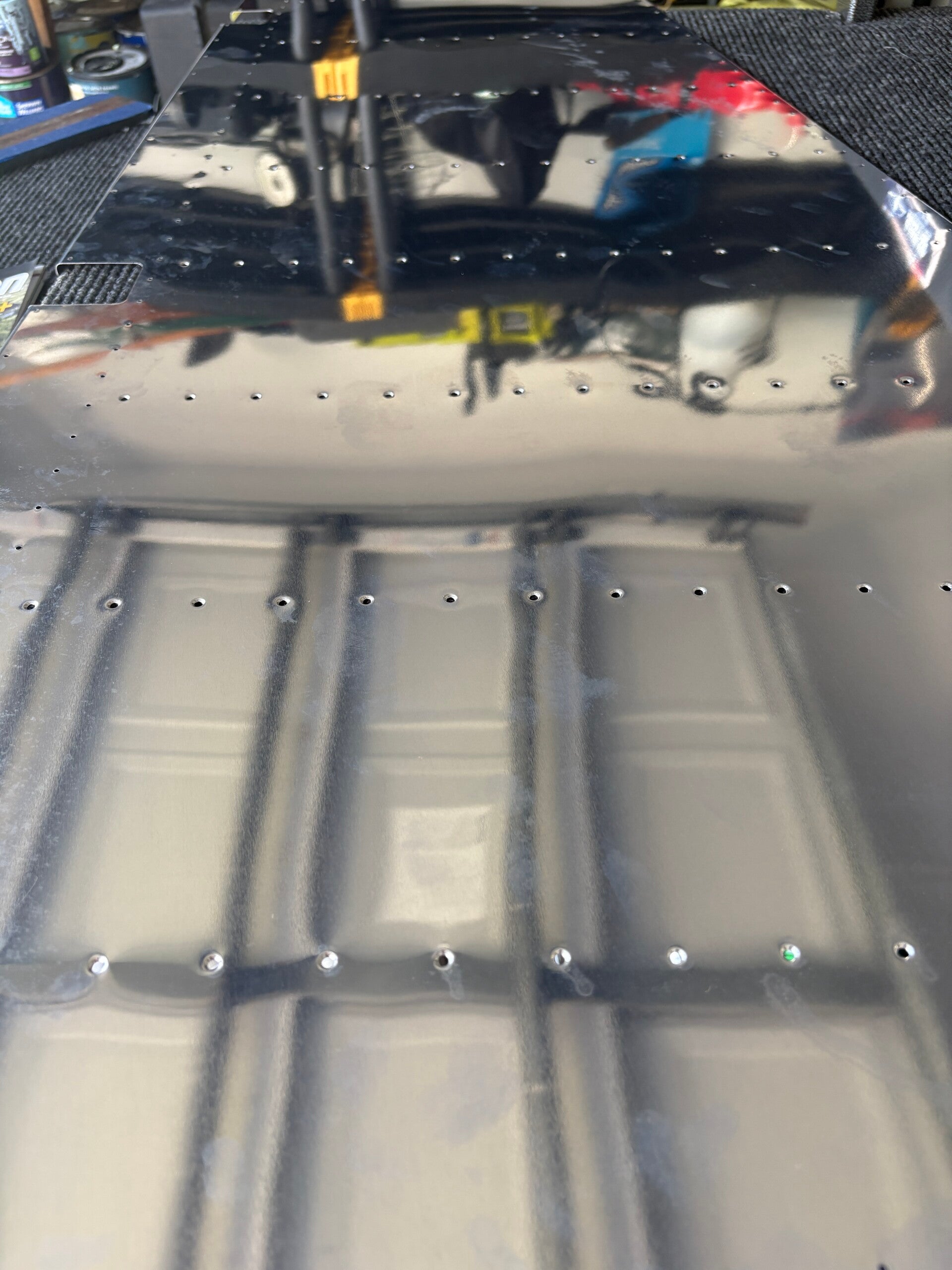
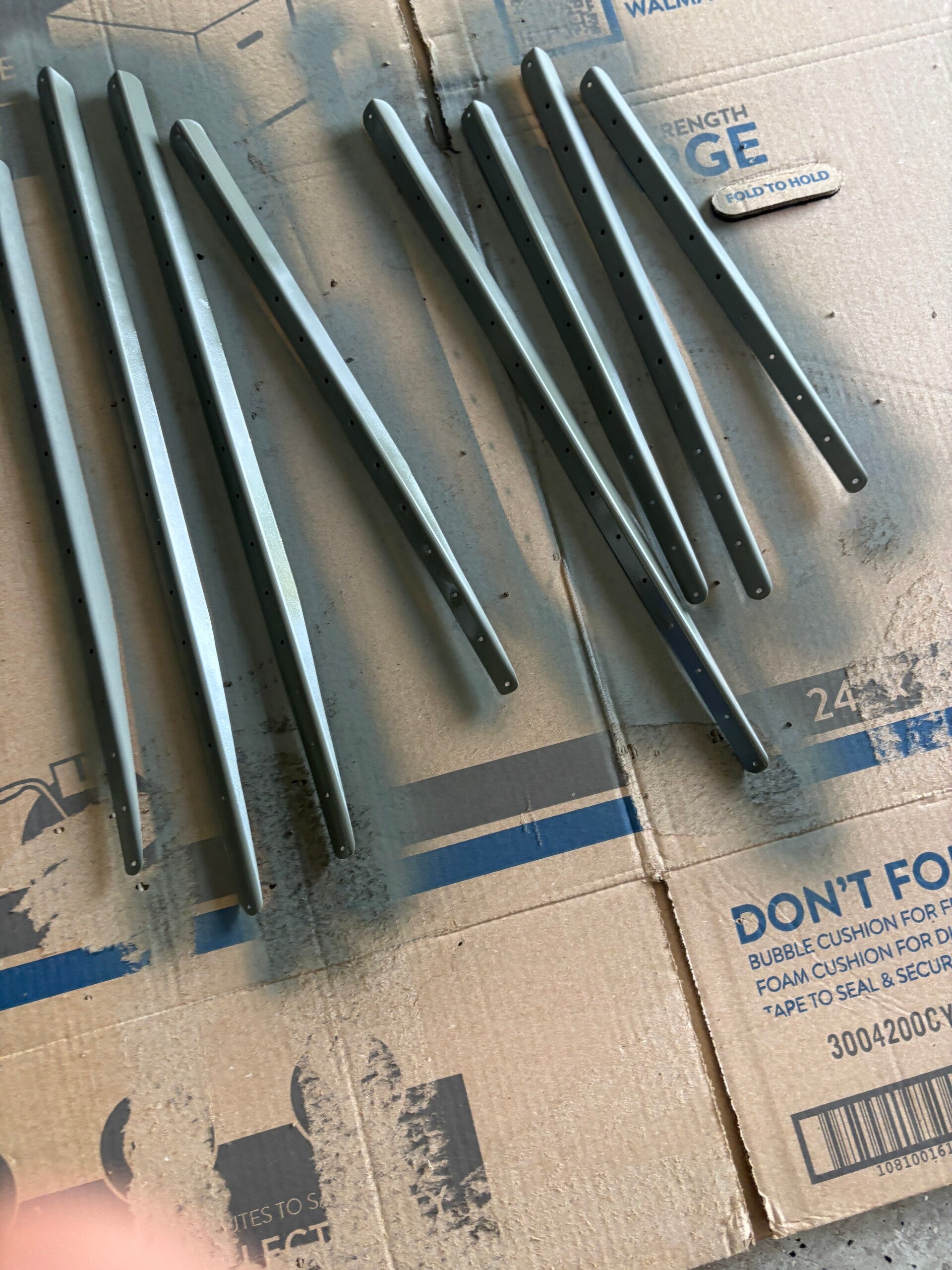
Fabricated the stiffeners, deburred, dimpled and primed. Same with the left skin.
6/17/2026 (1.5 hours)
Manual Section 6-5
Steps 10
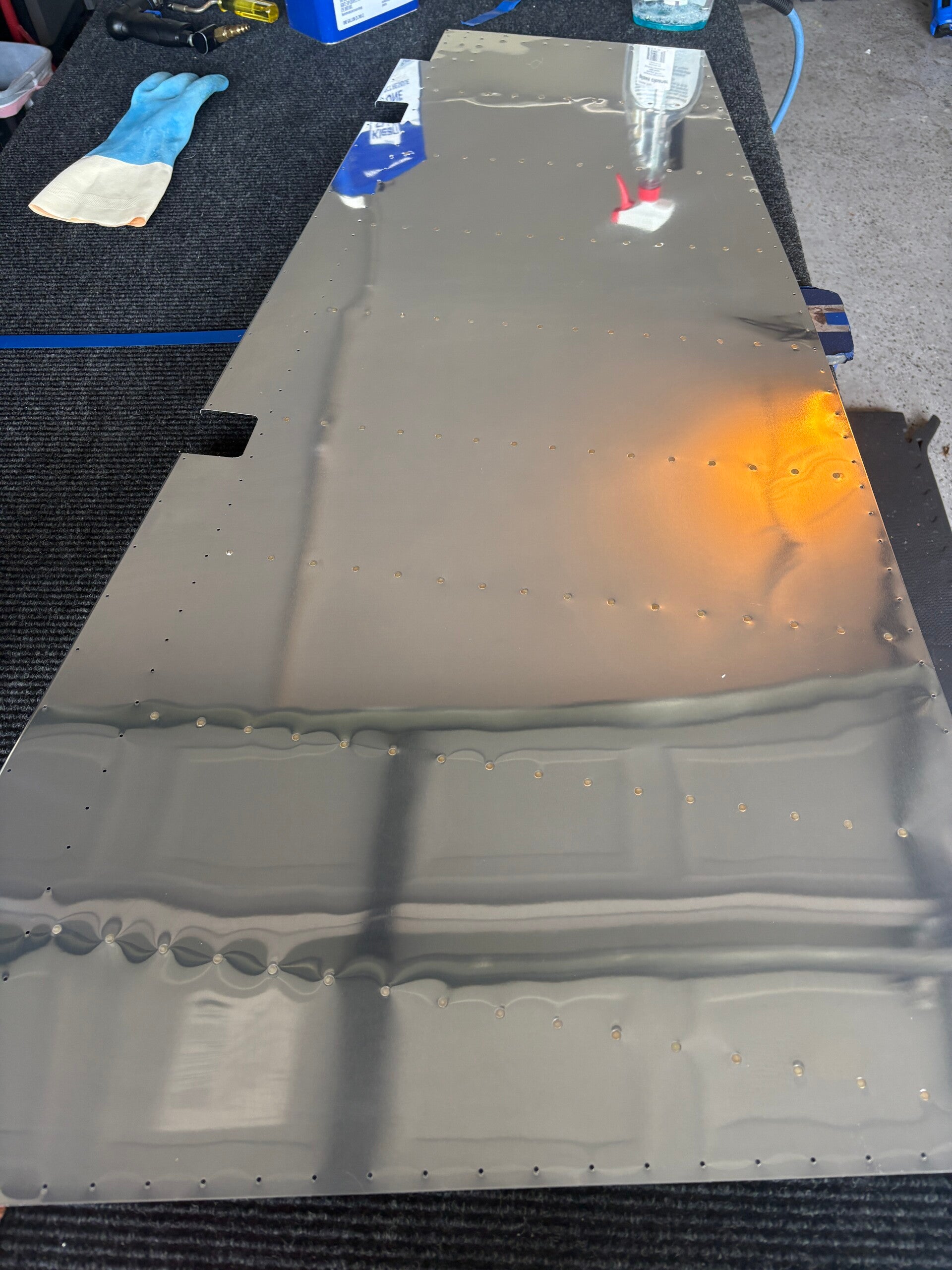
Back riveted the stiffener onto the left side rudder skin. Clecoed the skins to the skeleton and the R-916 rudder trailing edge in preparation for drilling.
6/19 - 7/20/2026 (12 hours)
Manual Section 6-6 and 6-7
Steps 11-17: Building the Rudder, Steps 1-7: Riveting the Rudder, Steps 1-3: Completing the Leading Edge of the Rudder
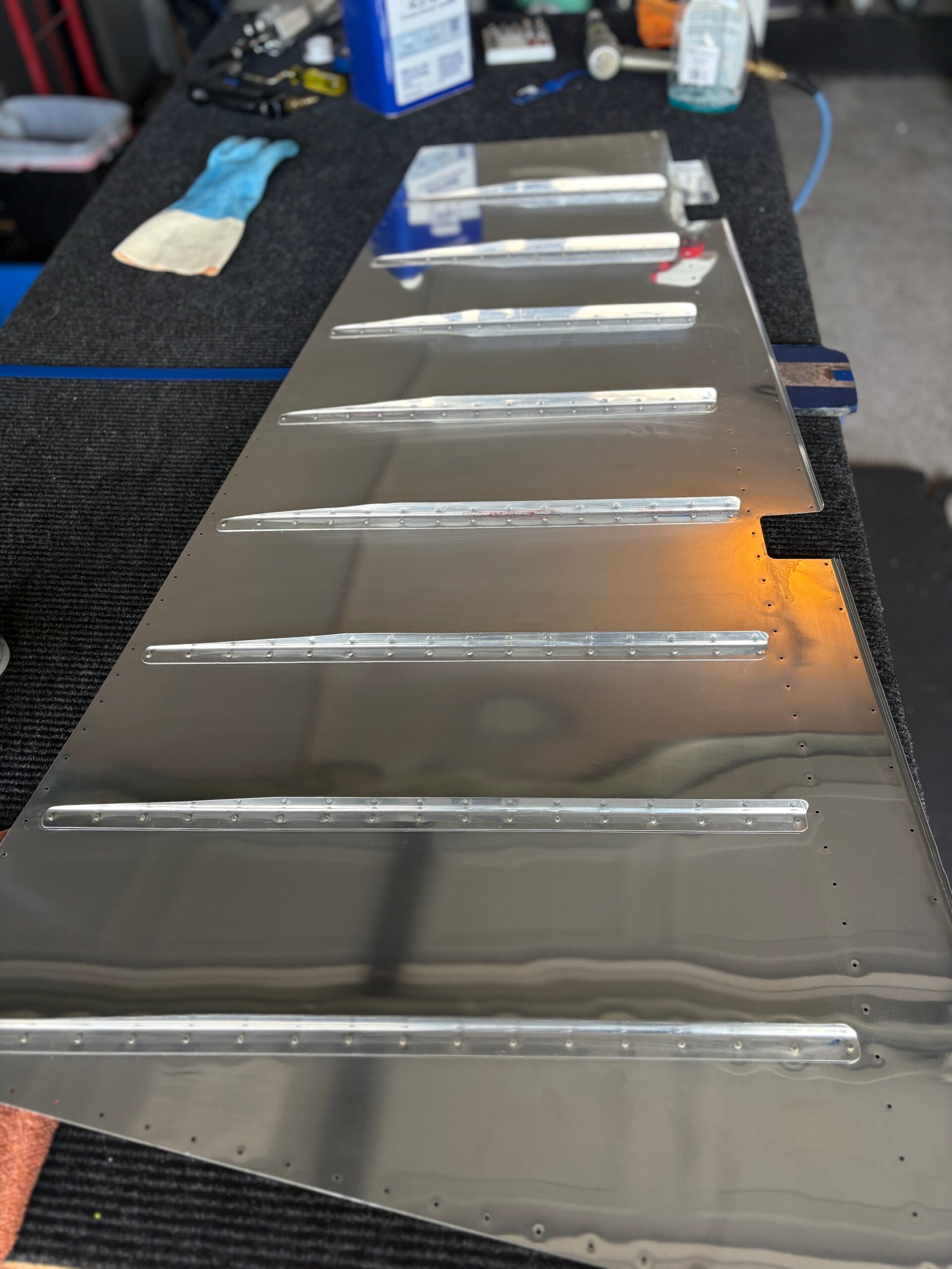
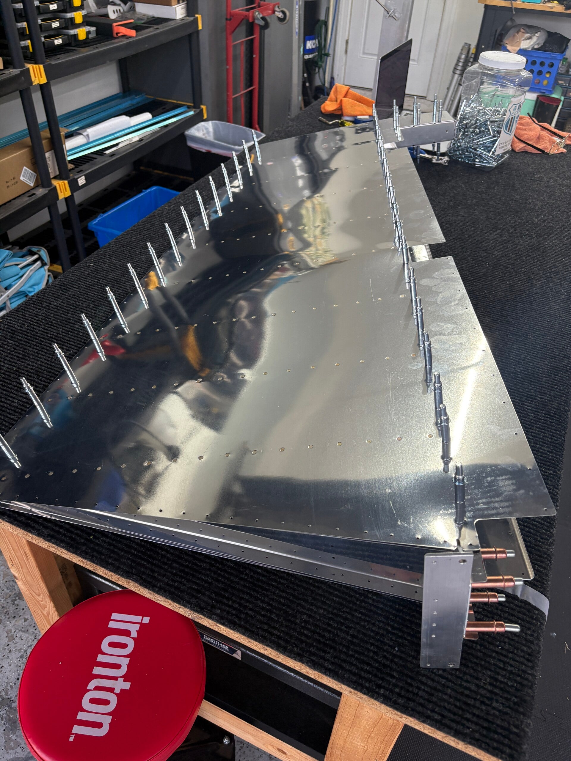
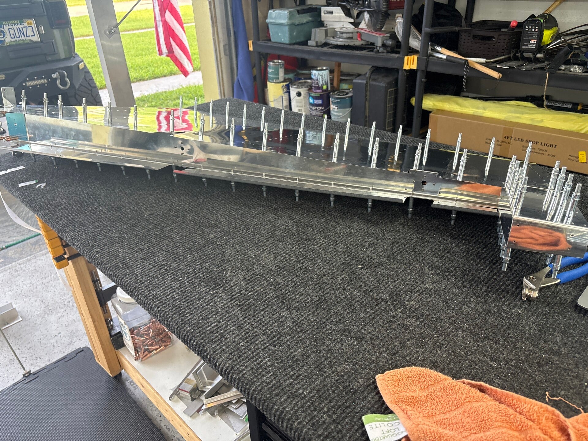
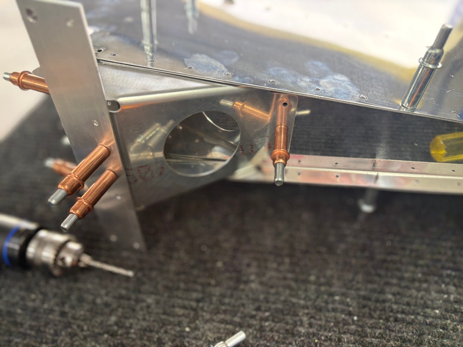
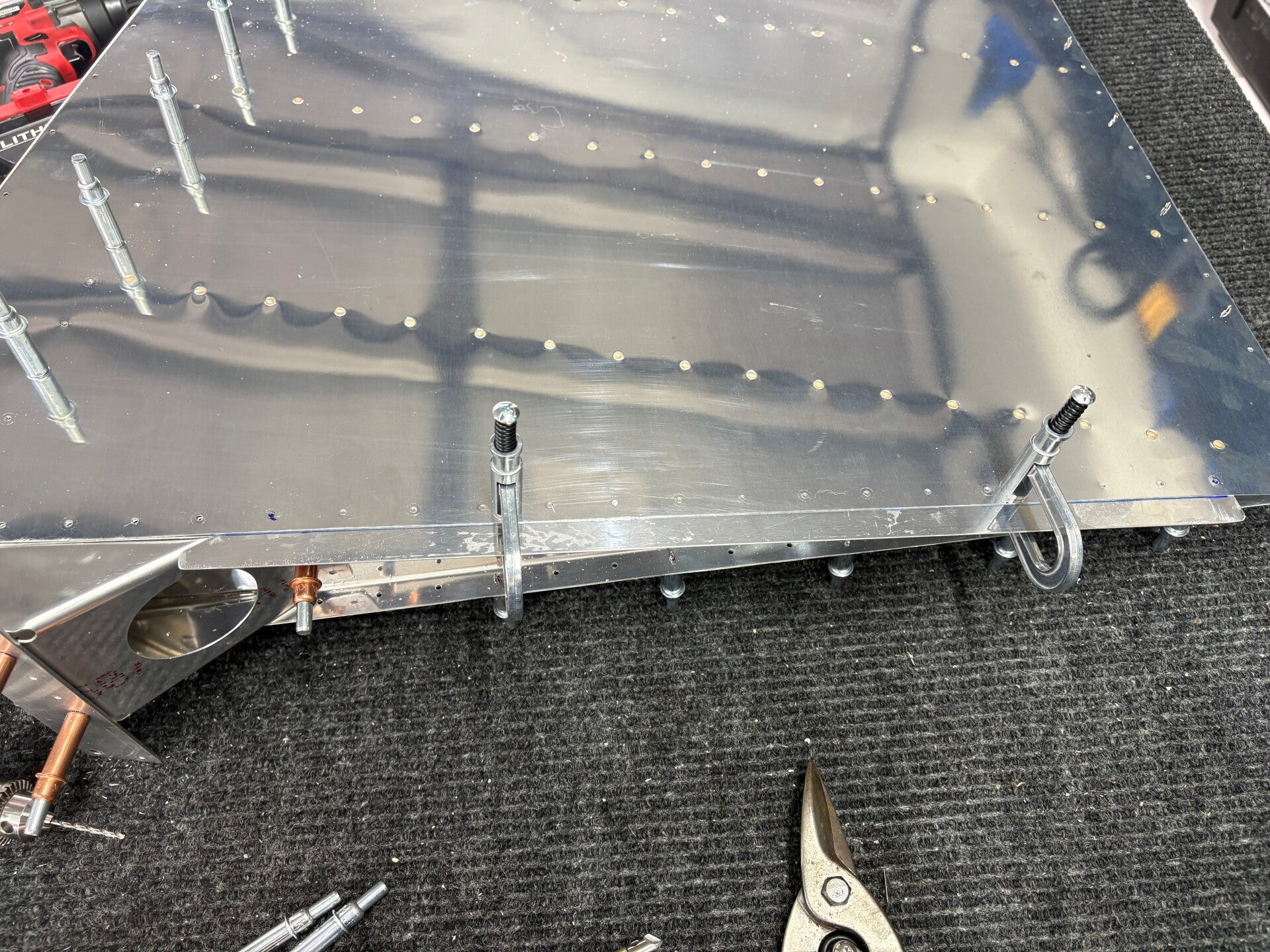
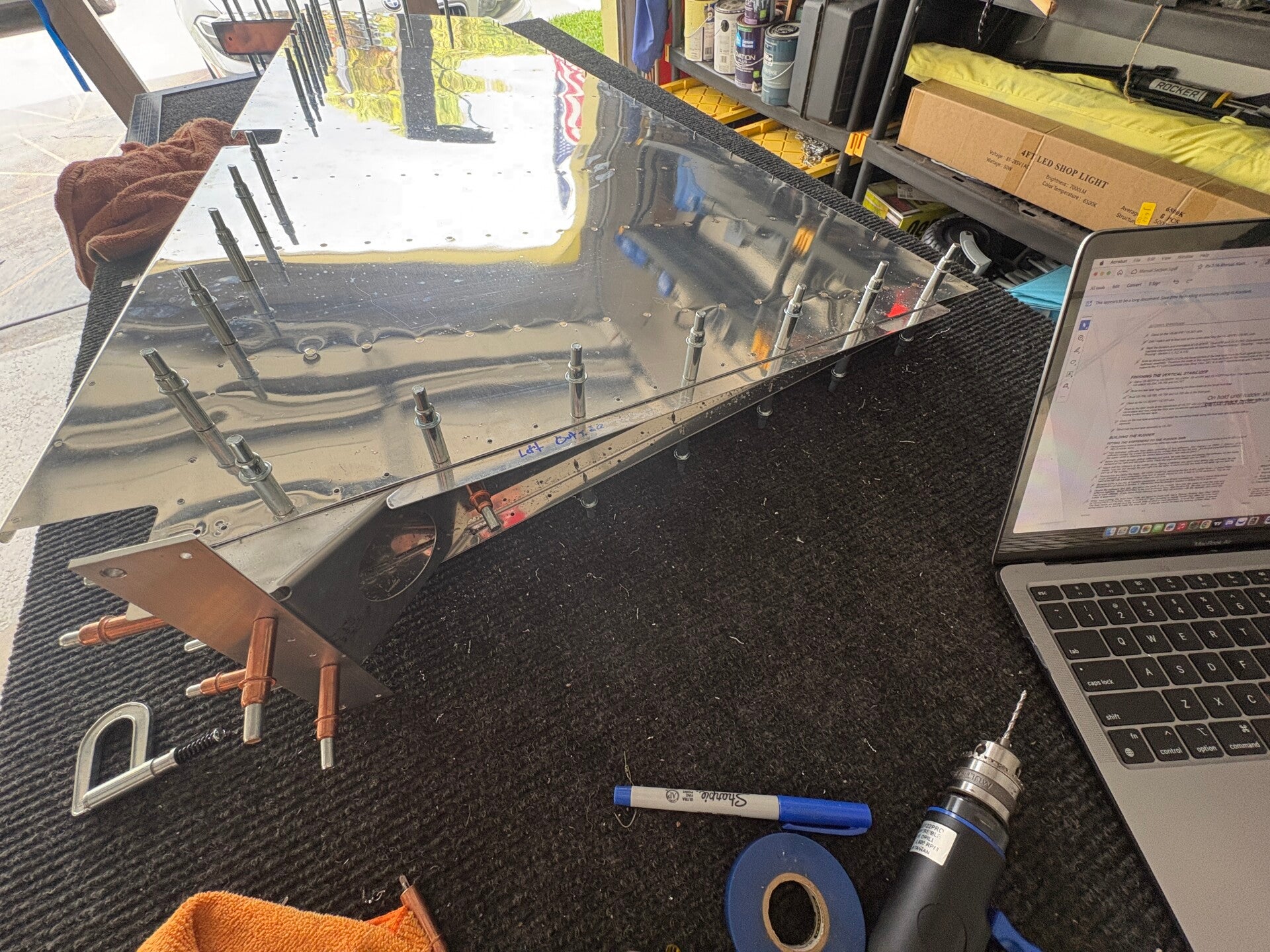
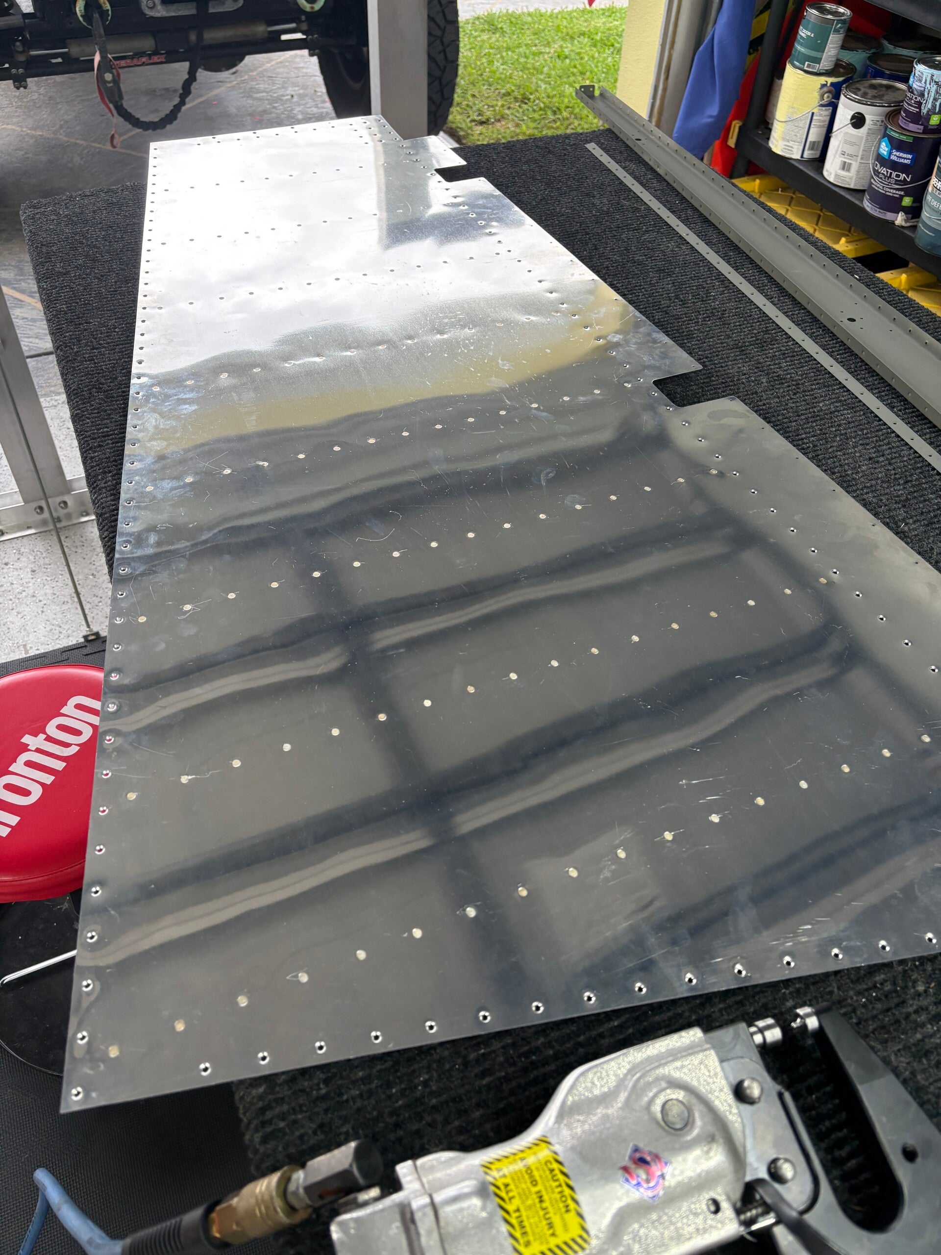
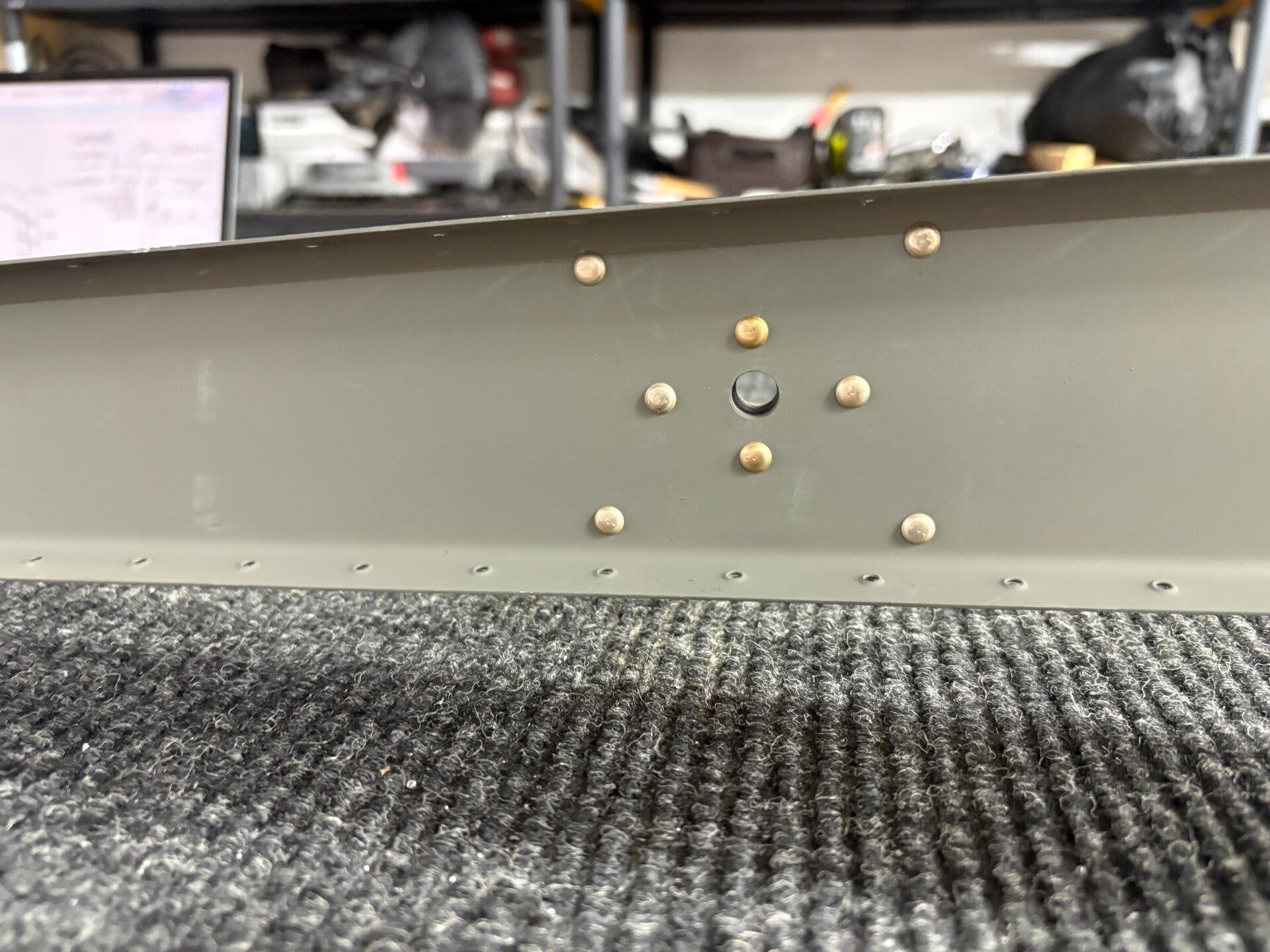
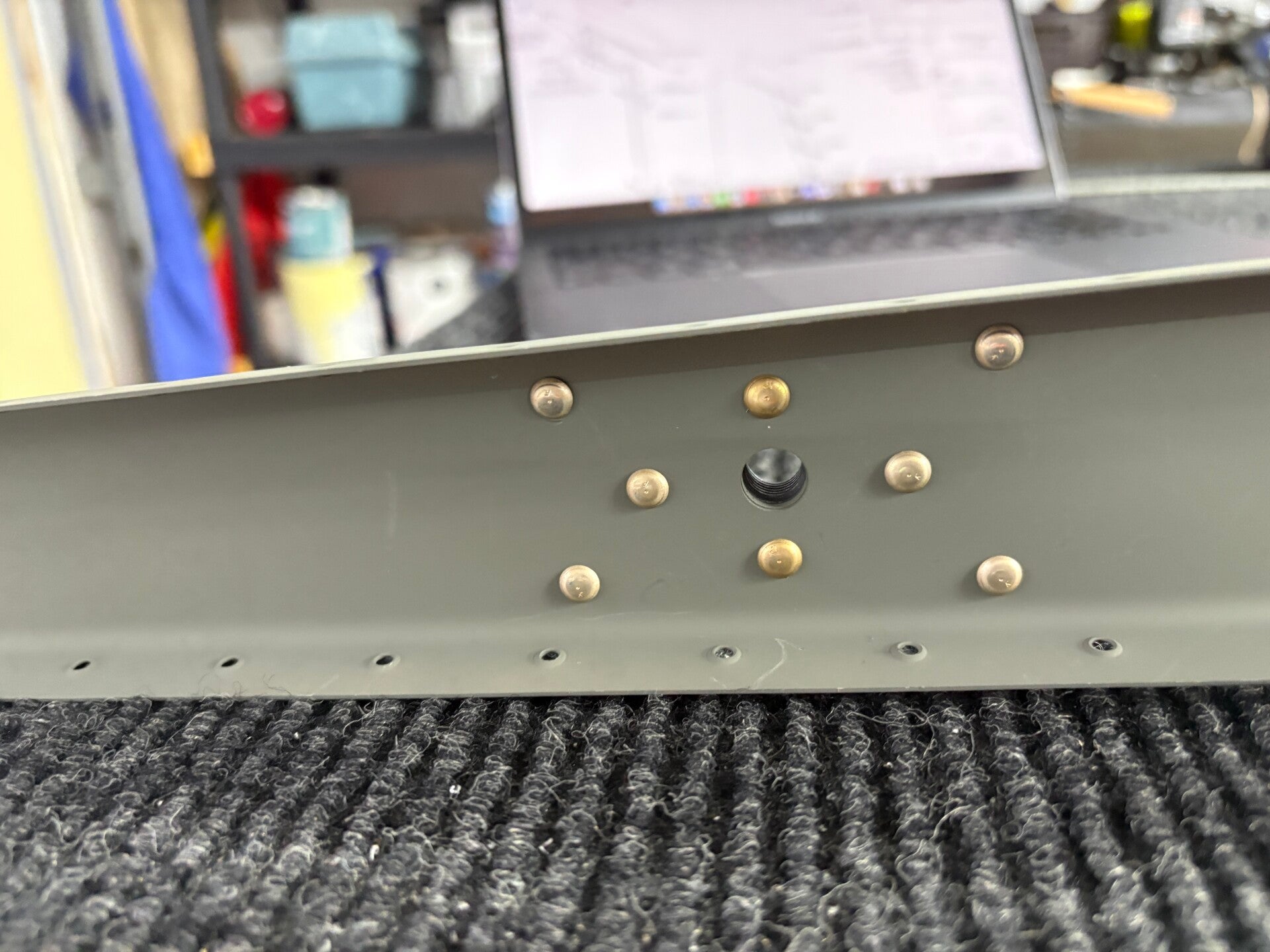
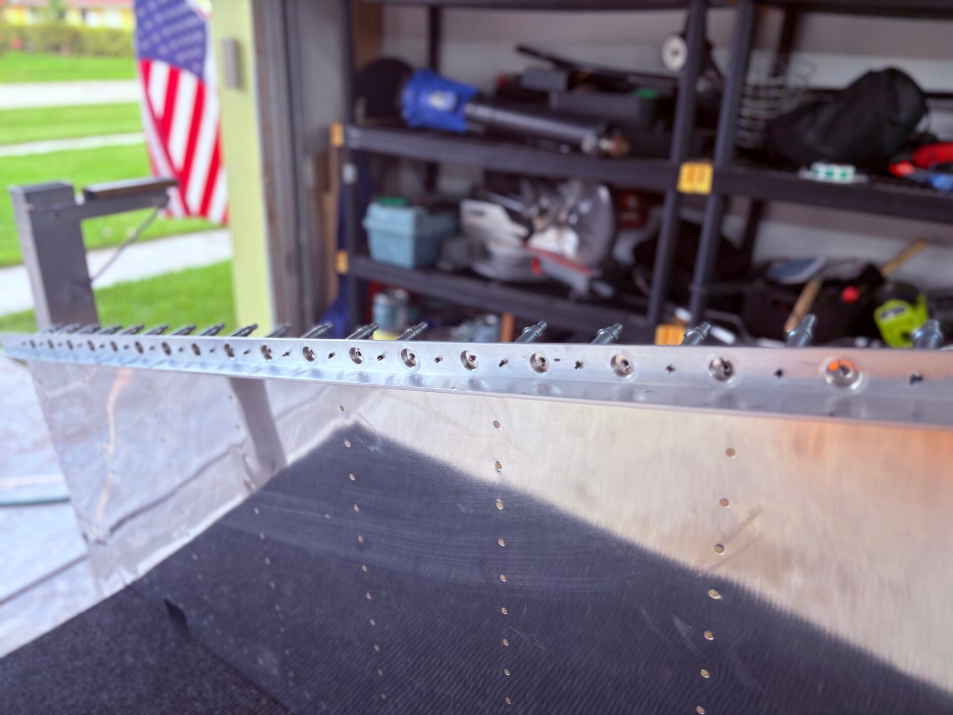
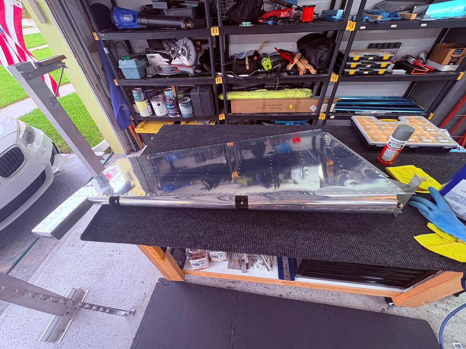
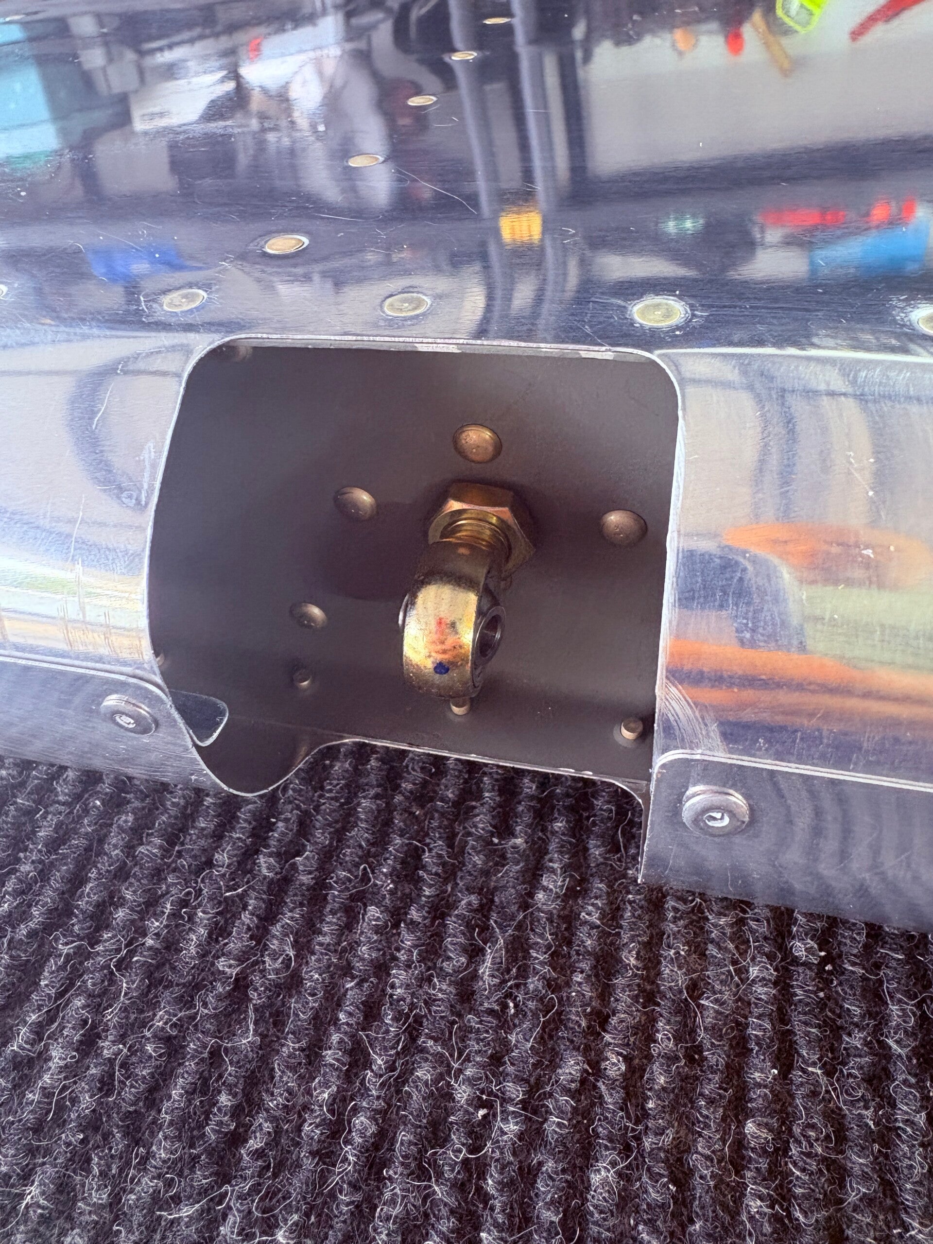
After taking a break from updating the website, I’ve made significant progress on the rudder, with just one rivet hole left to tackle in a particularly tight spot. I plan to seek advice from the local EAA chapter on how to proceed with that. My time was spent constructing the rudder, which included fabricating essential parts like the bottom attach strips and shaping the rudder brace. Once everything was assembled, I disassembled it again to deburr, dimple, and prime the components.
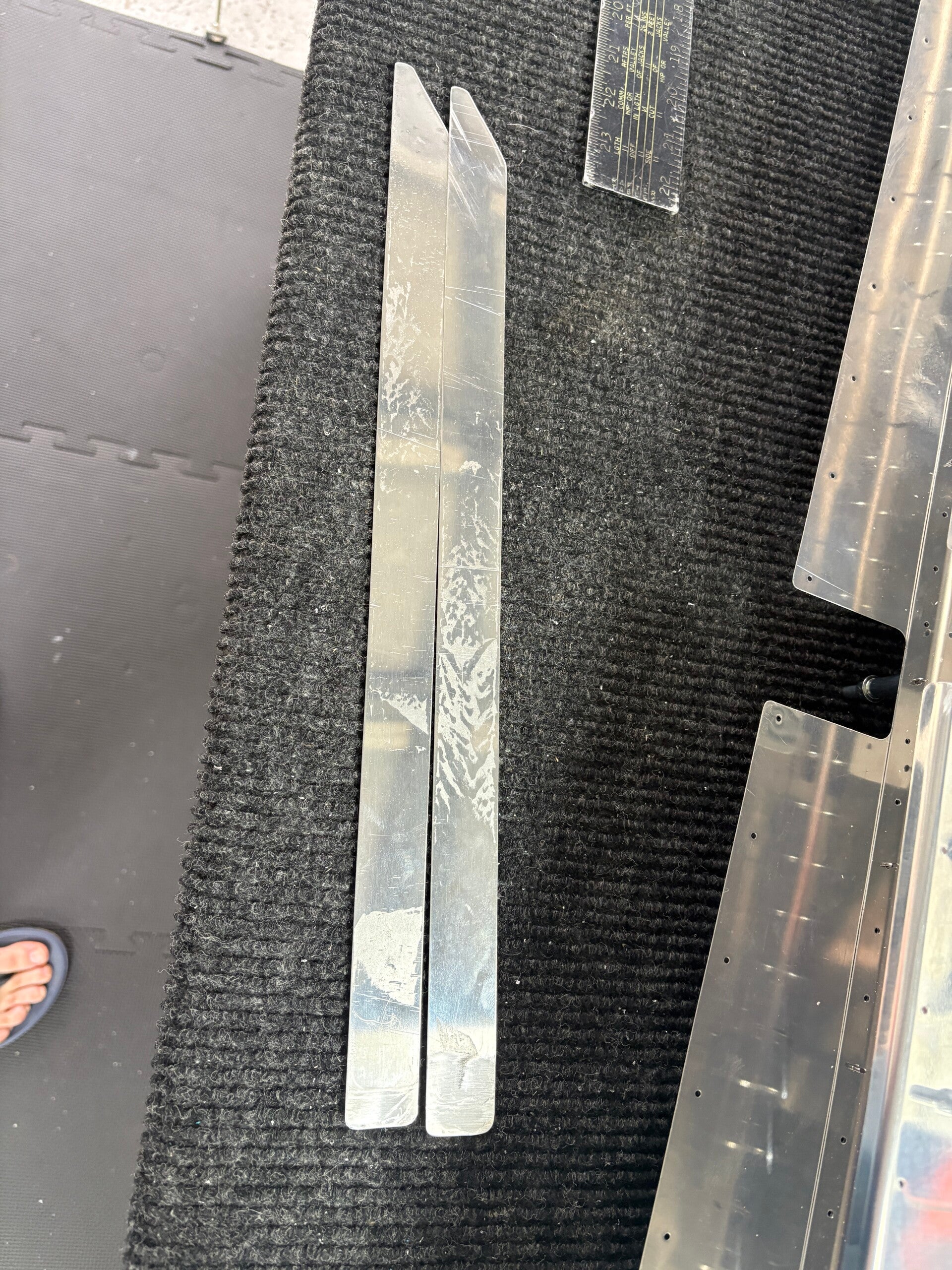
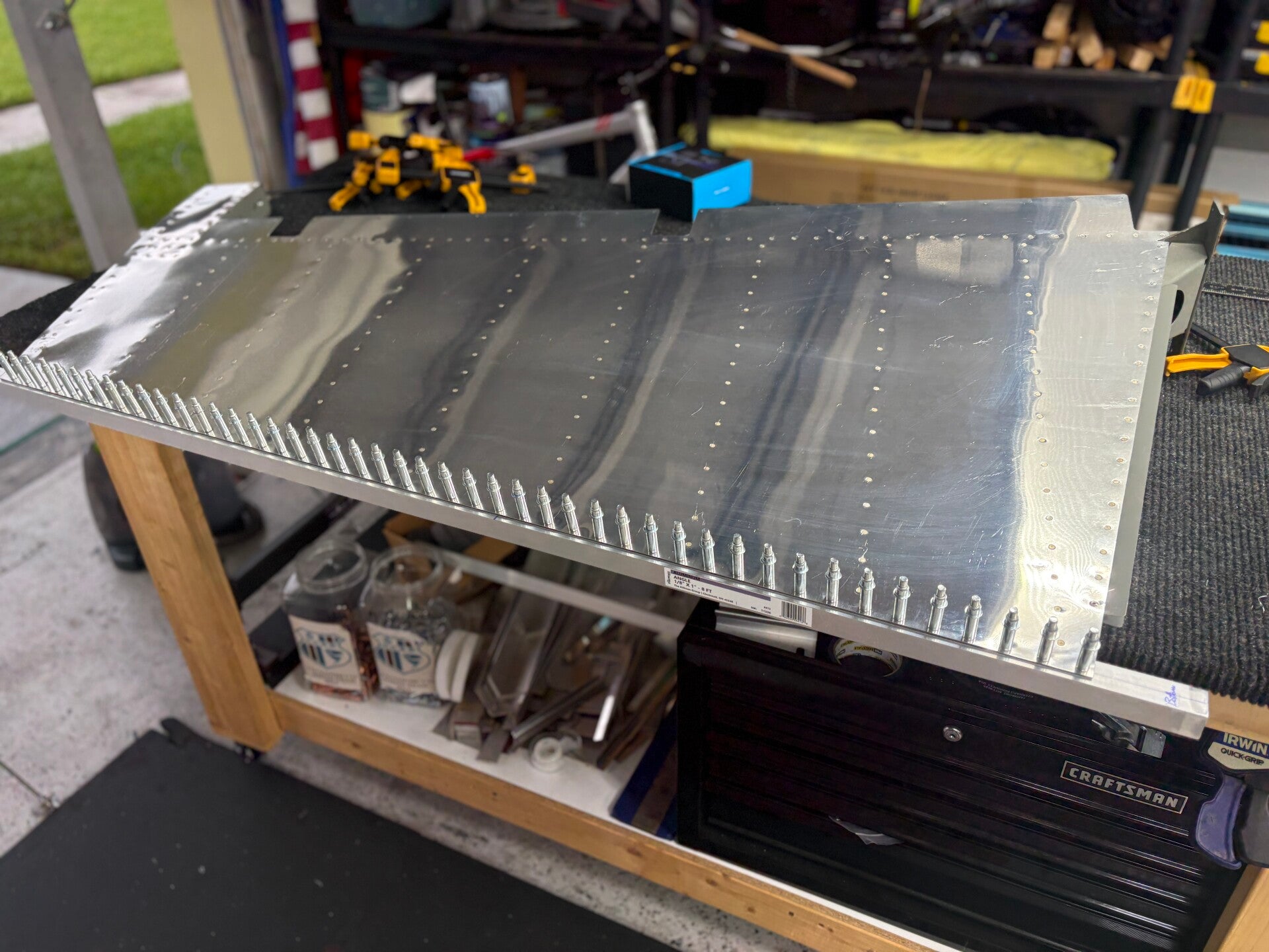
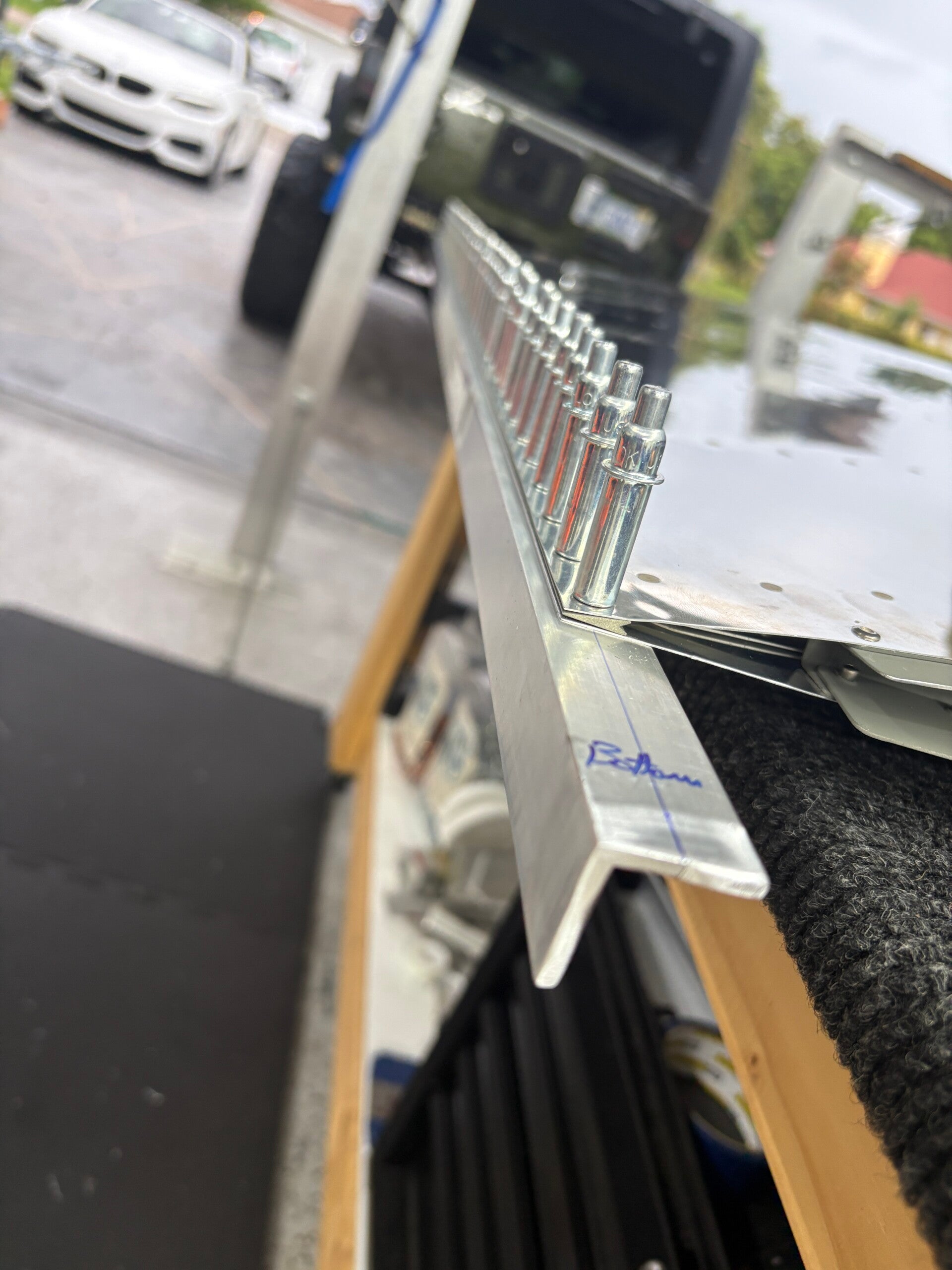
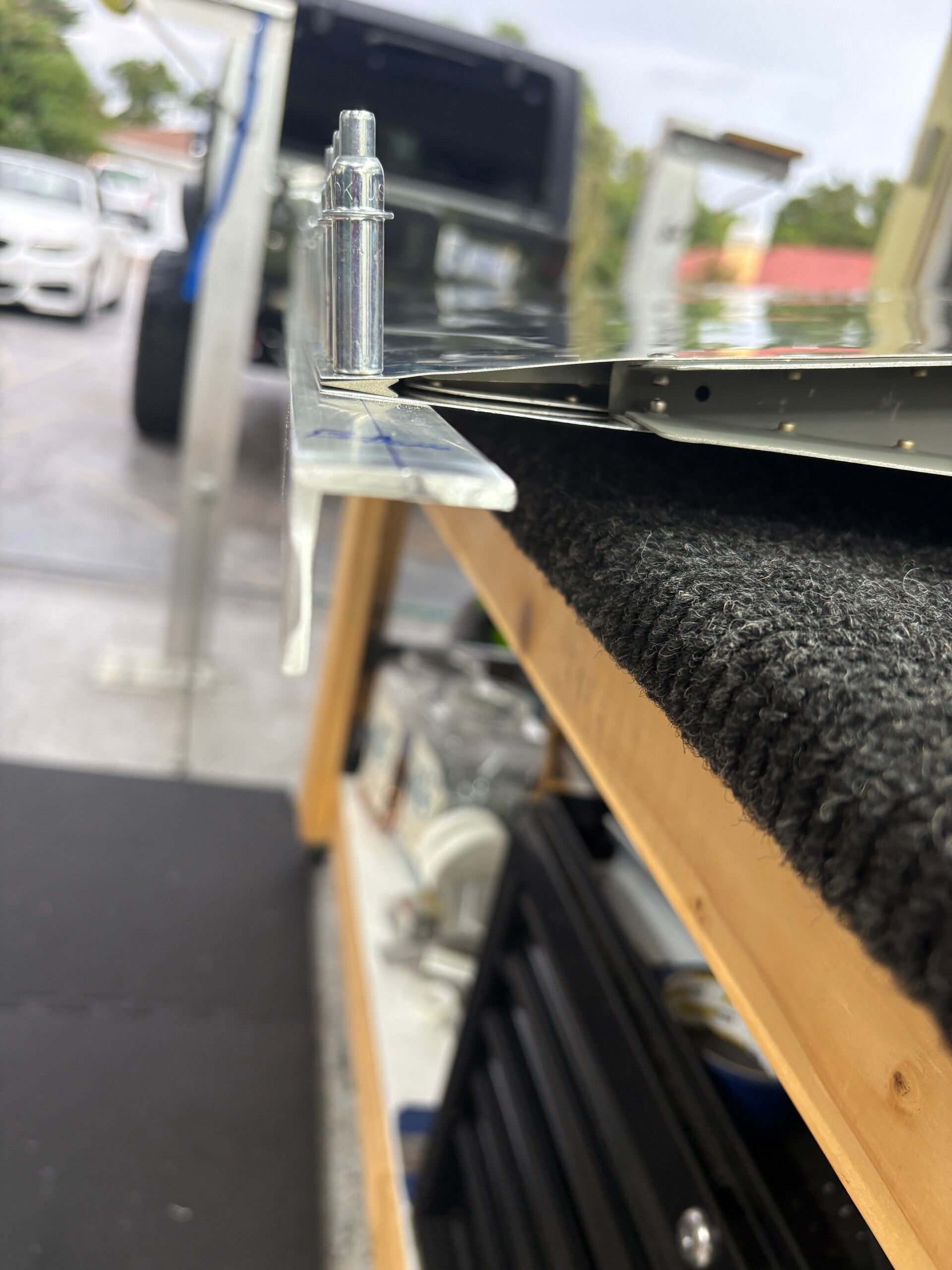
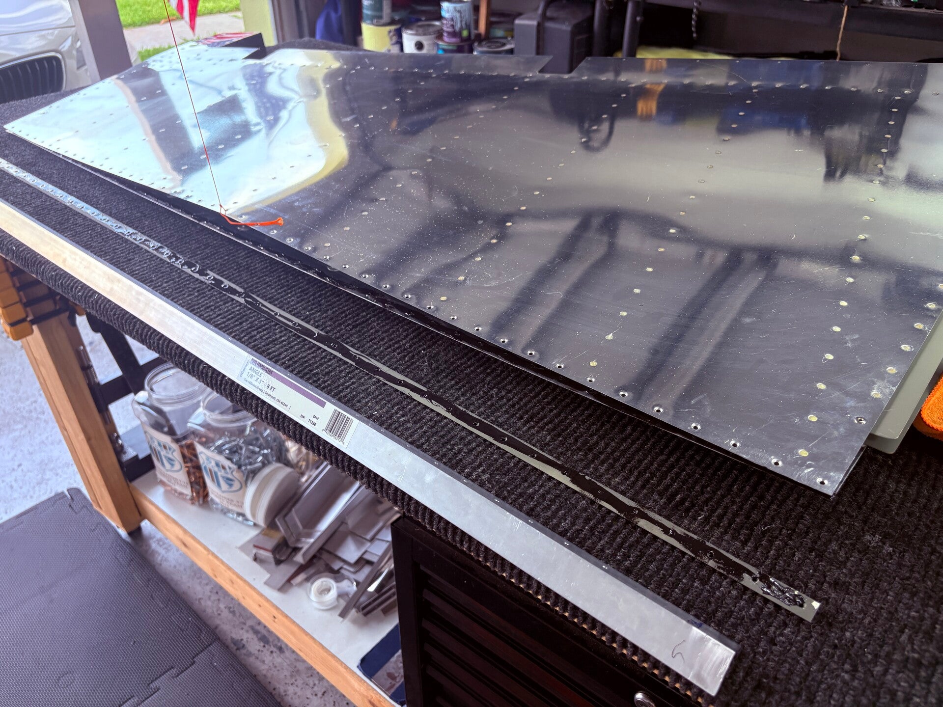
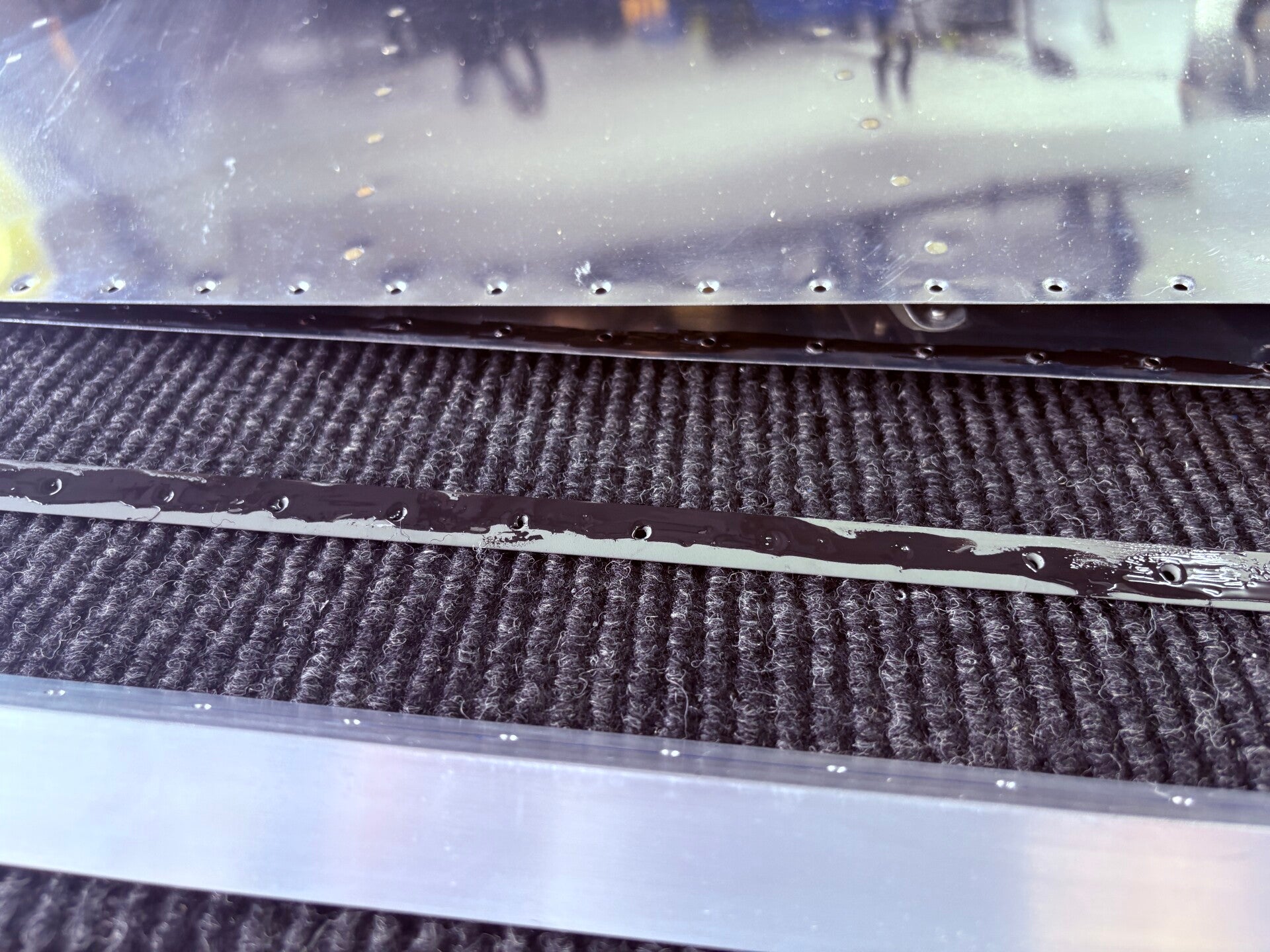
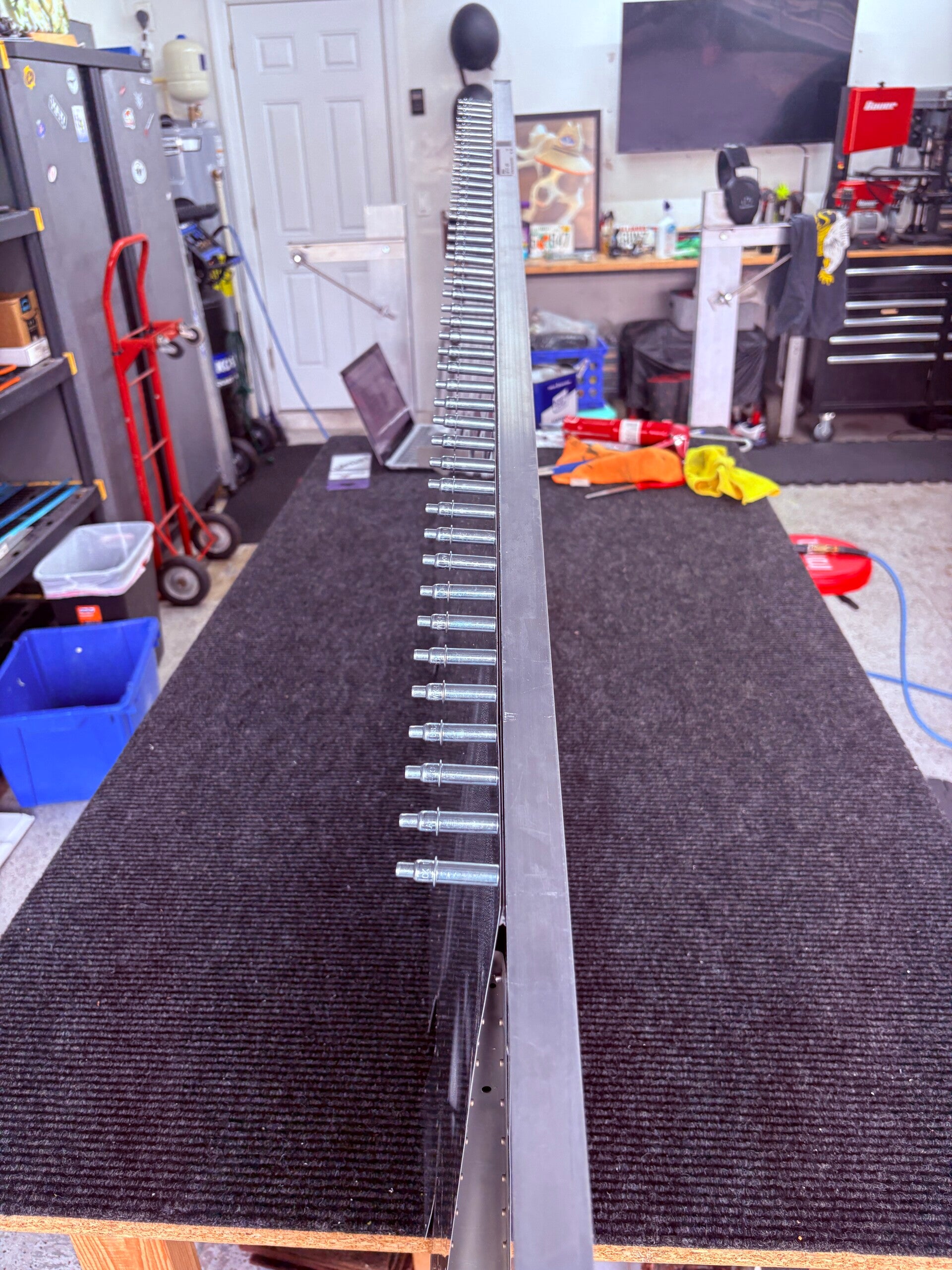
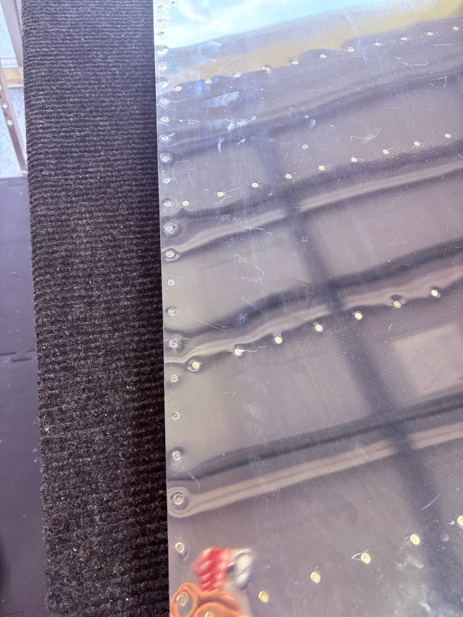
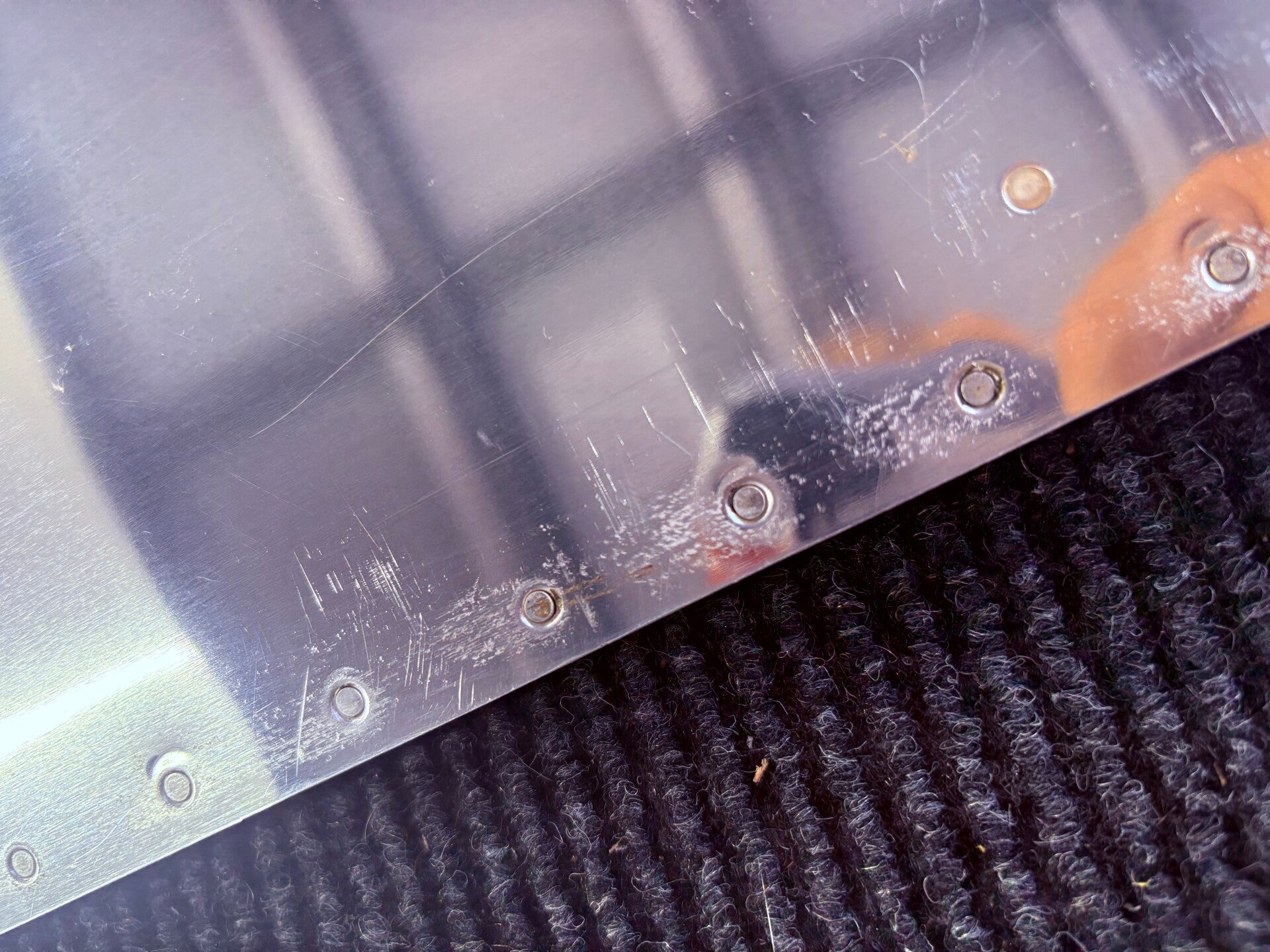
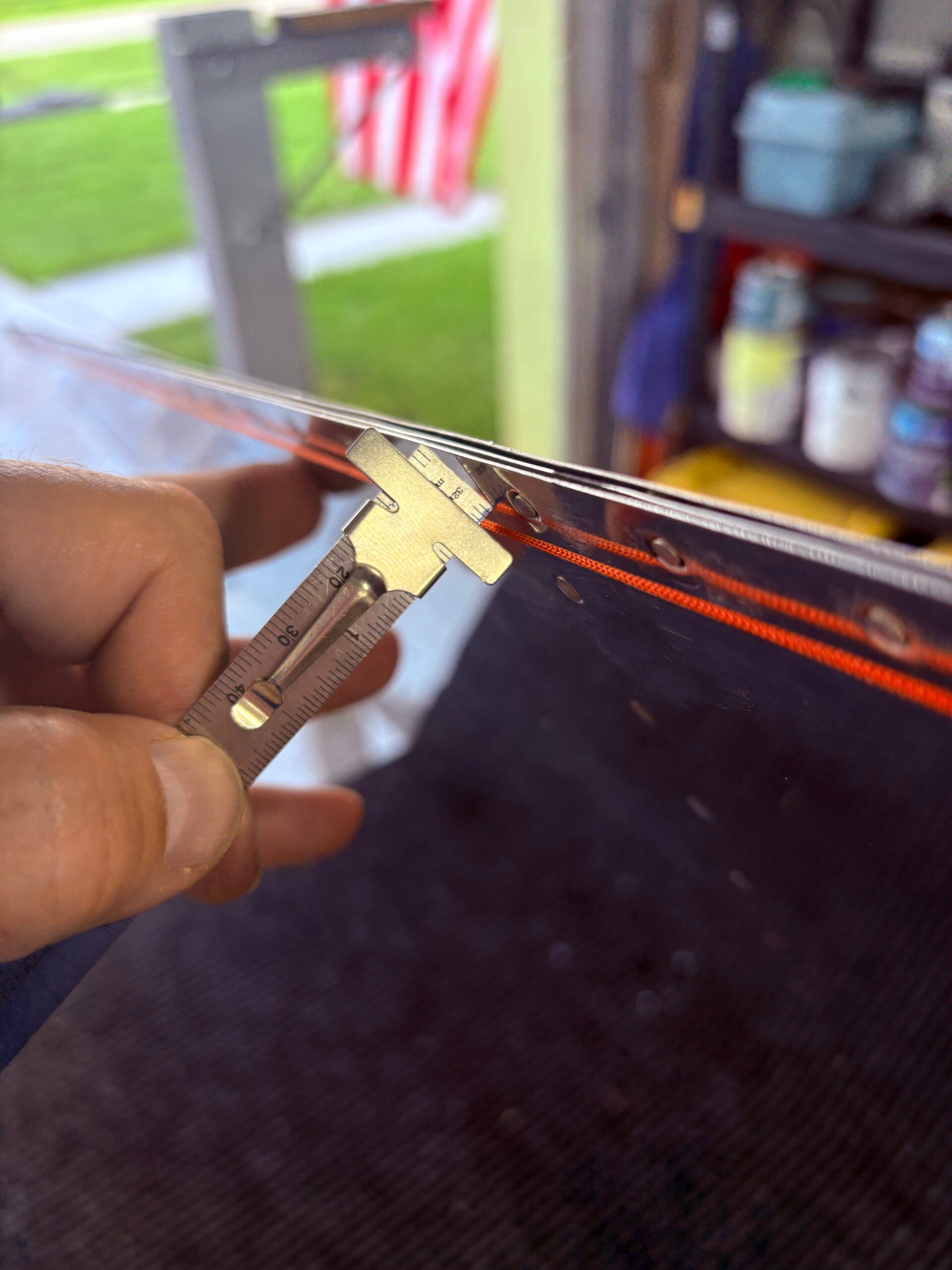
The next major step involved riveting everything together, particularly focusing on the trailing edge. My goal was to ensure it remained as straight as possible, as the thin metal can easily warp. To prevent this, I used an aluminum angle, matched drilled it to the trailing edge, applied tank sealant to the AEX wedge, and then assembled it with the angle before riveting. While Van's provides a lengthy process for this, I discovered a much simpler method on Mike Bullock's page (see here for more details).
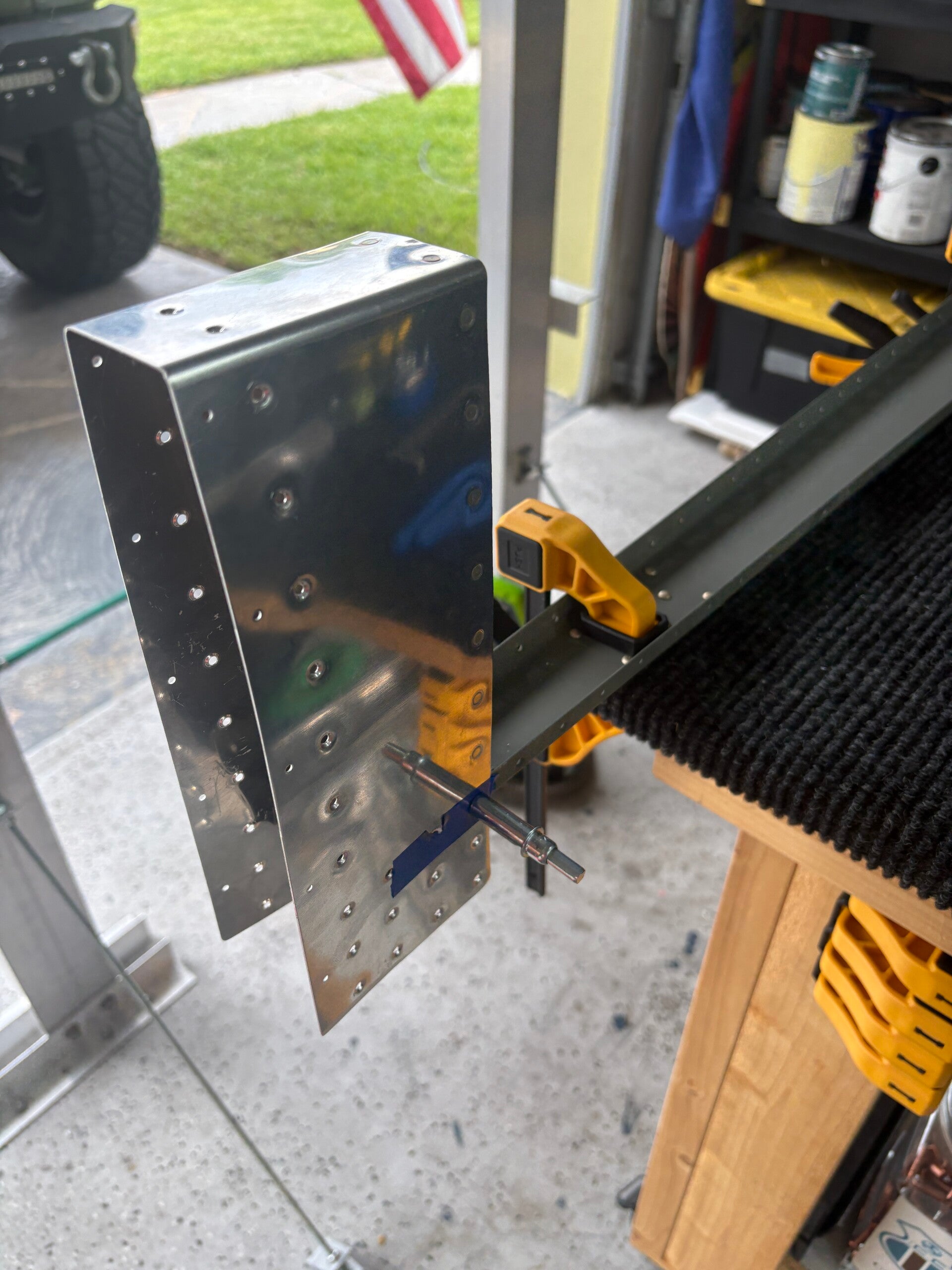
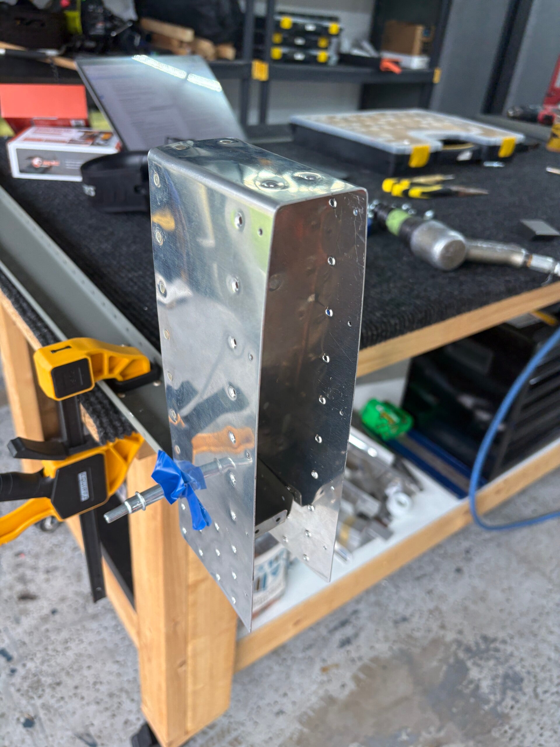
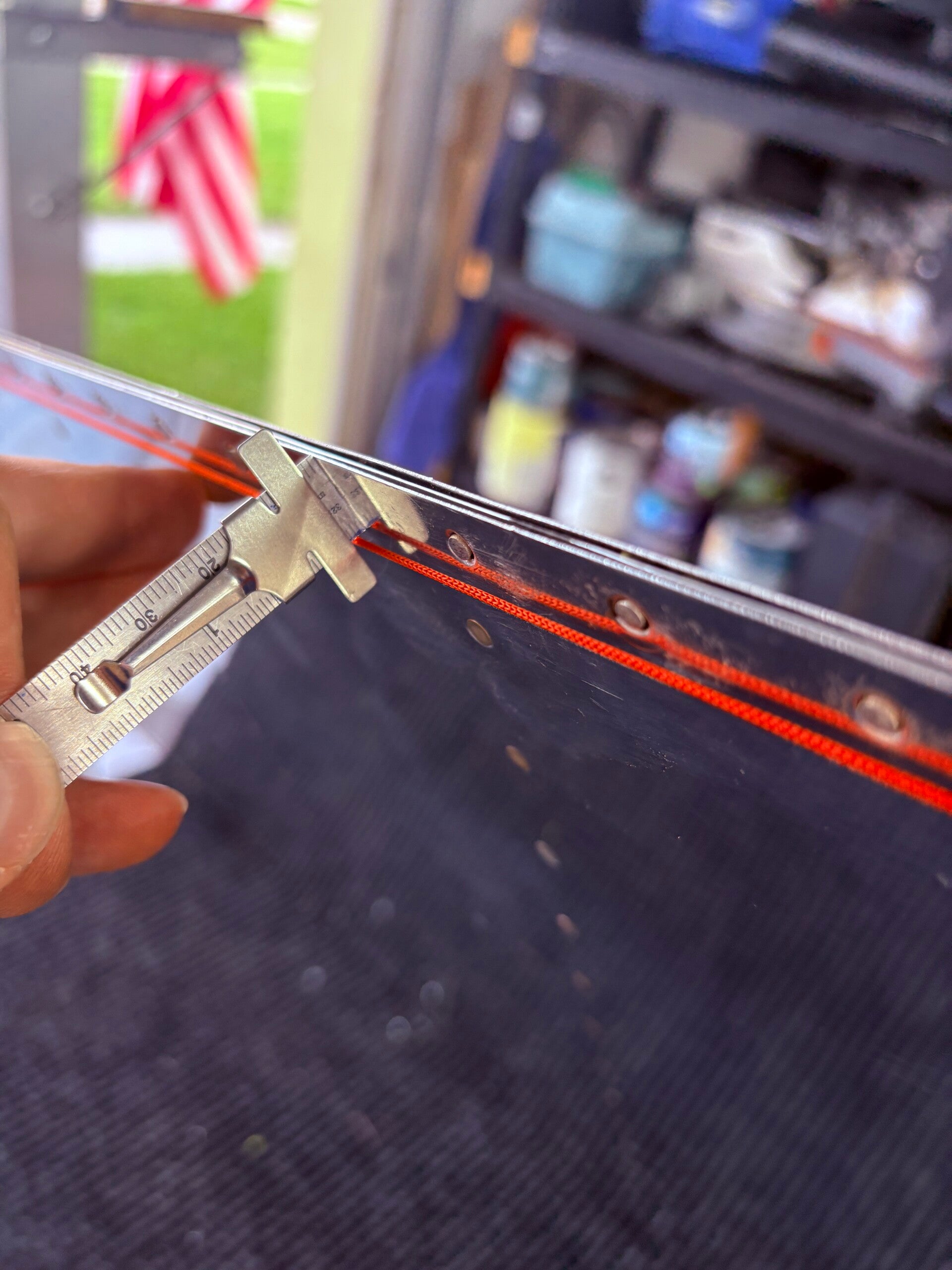
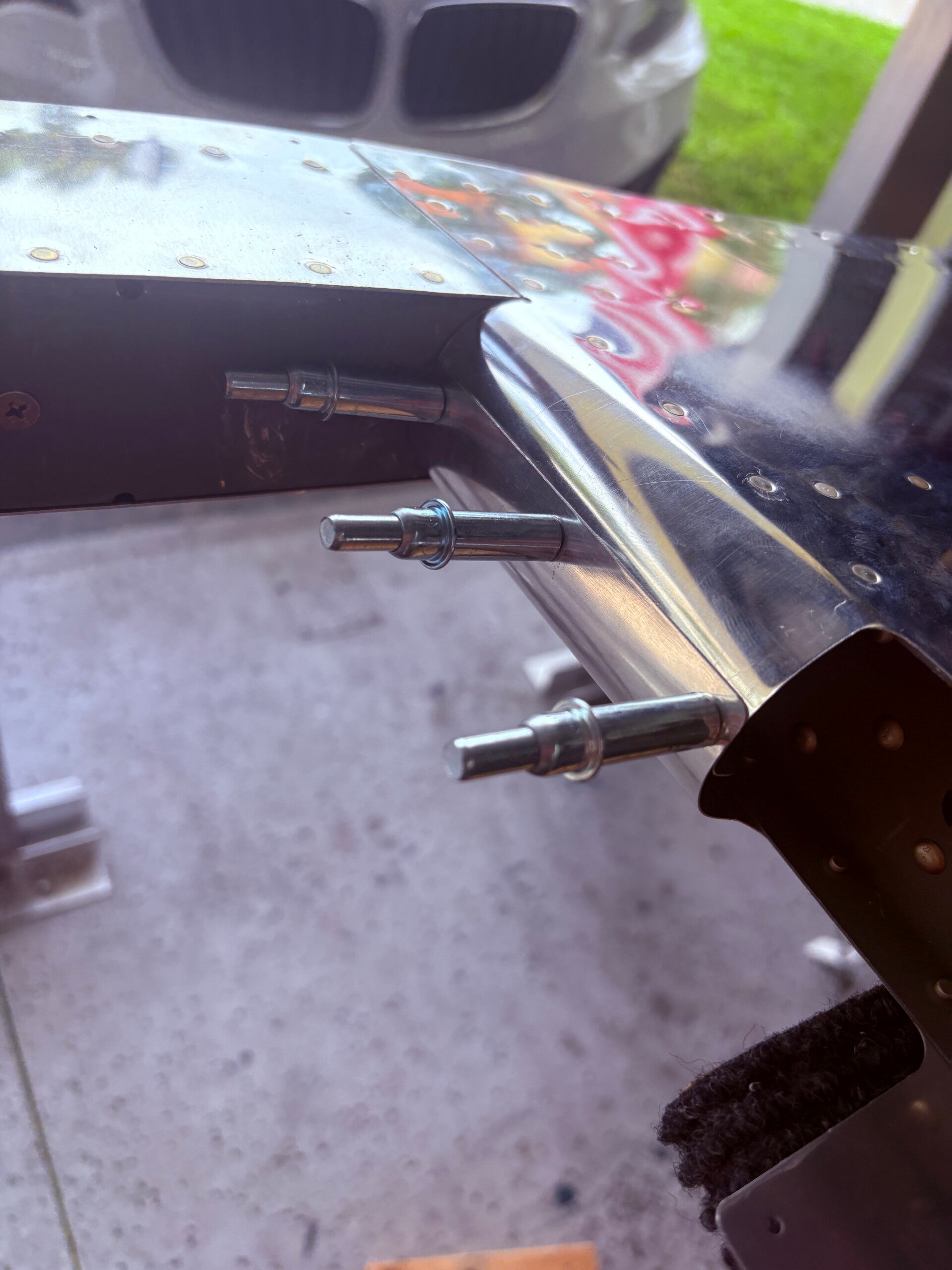
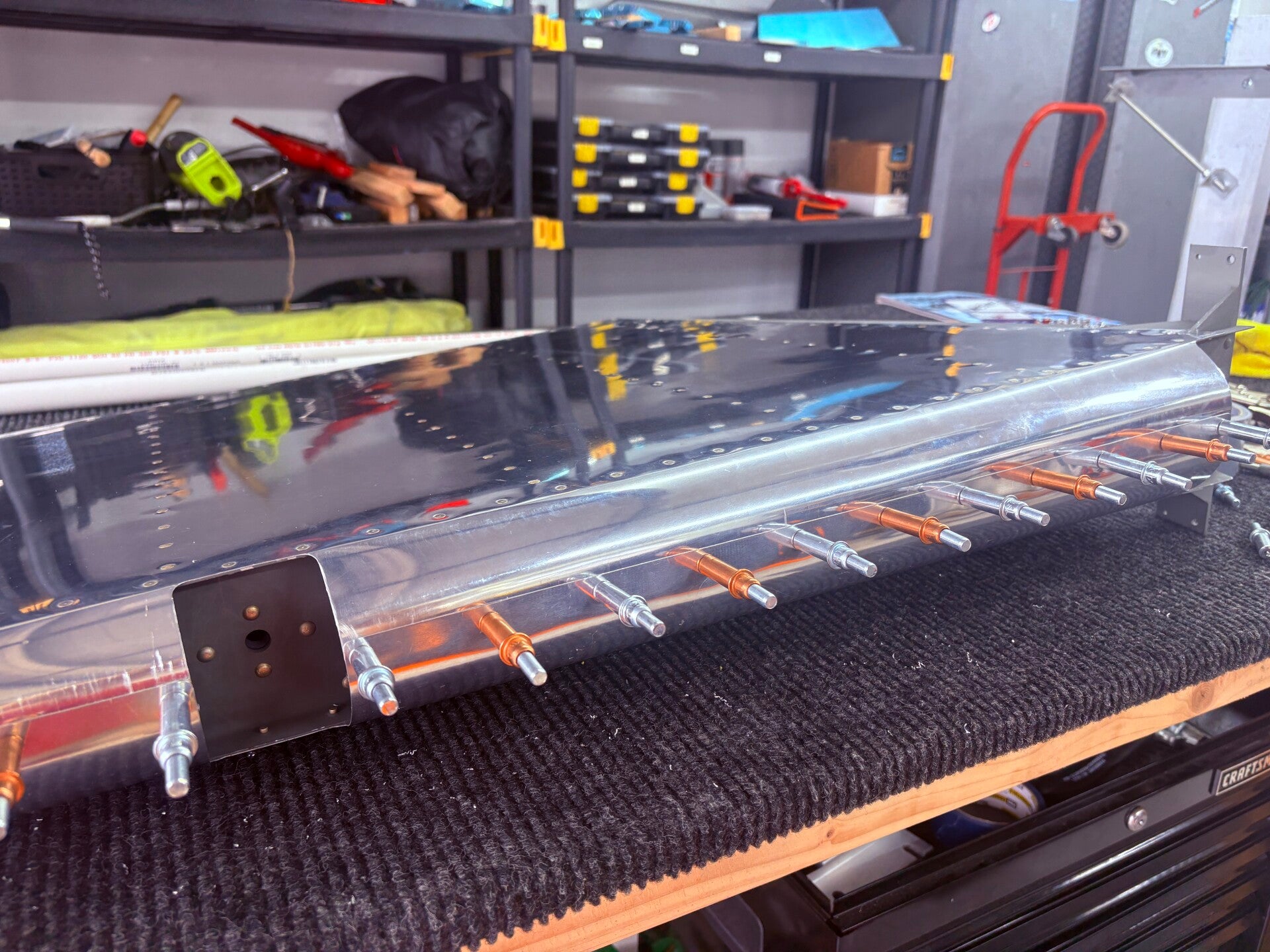
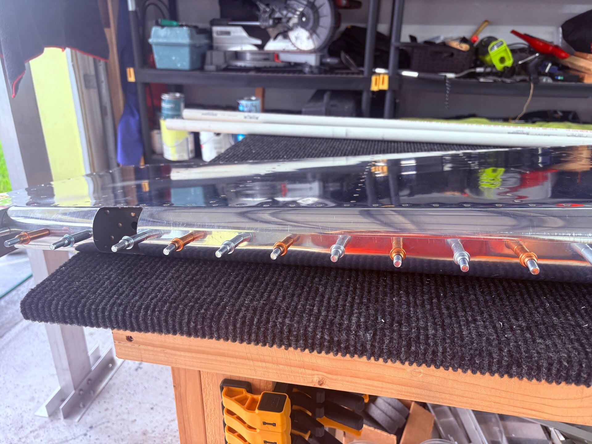
Next, I bent the leading edge, which required a 1-inch pipe, plenty of duct tape, and a lot of twisting to achieve the correct form. It wasn’t easy, but I think the result turned out well. Only time will tell (10-20 years) if I encounter any cracking around the joints, as the purpose of the bending is to alleviate pressure where the two parts meet for riveting.
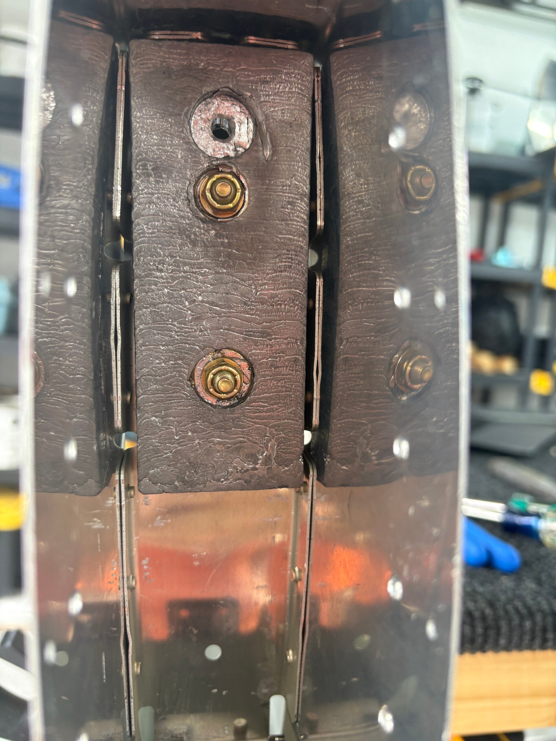
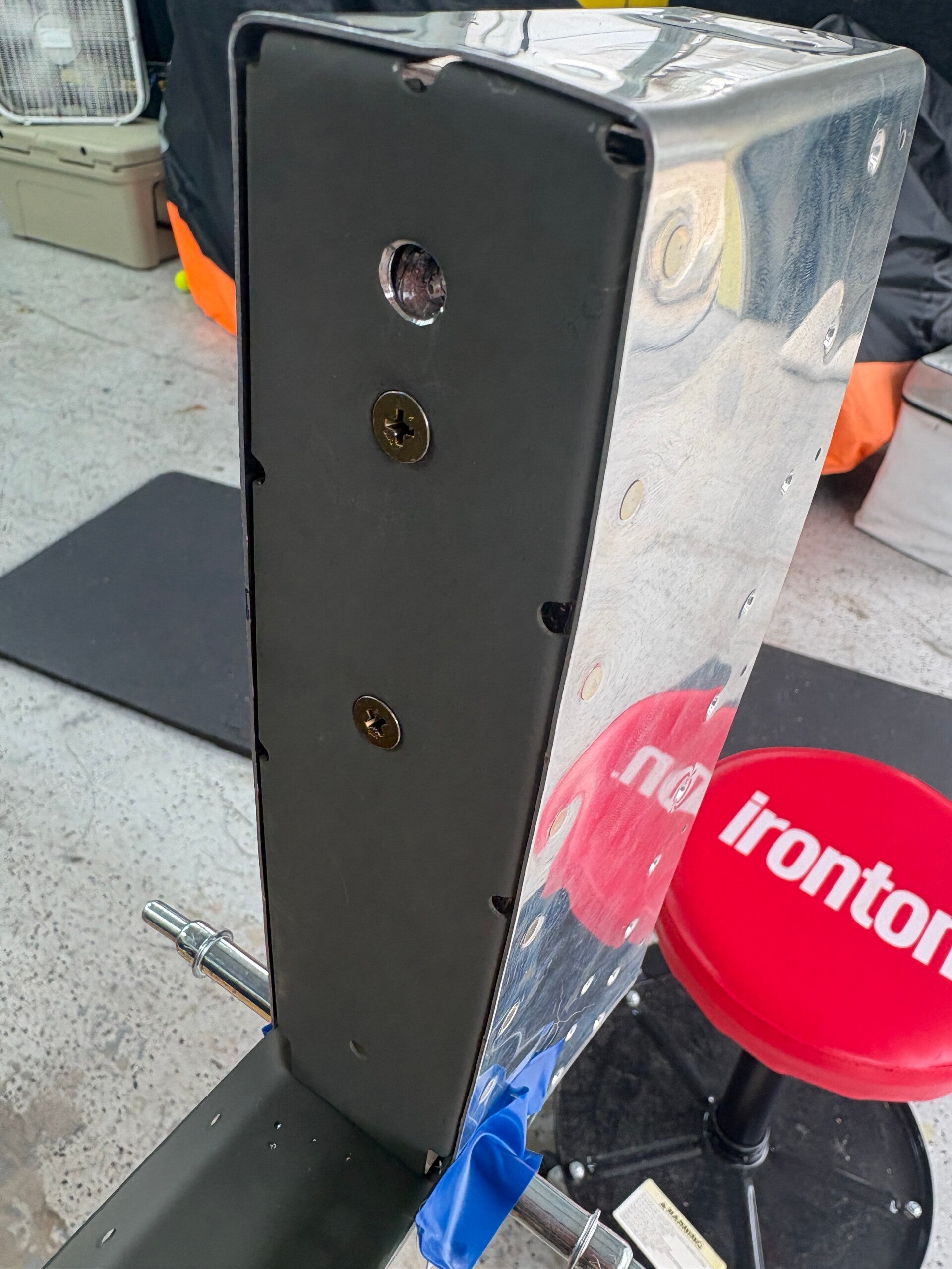
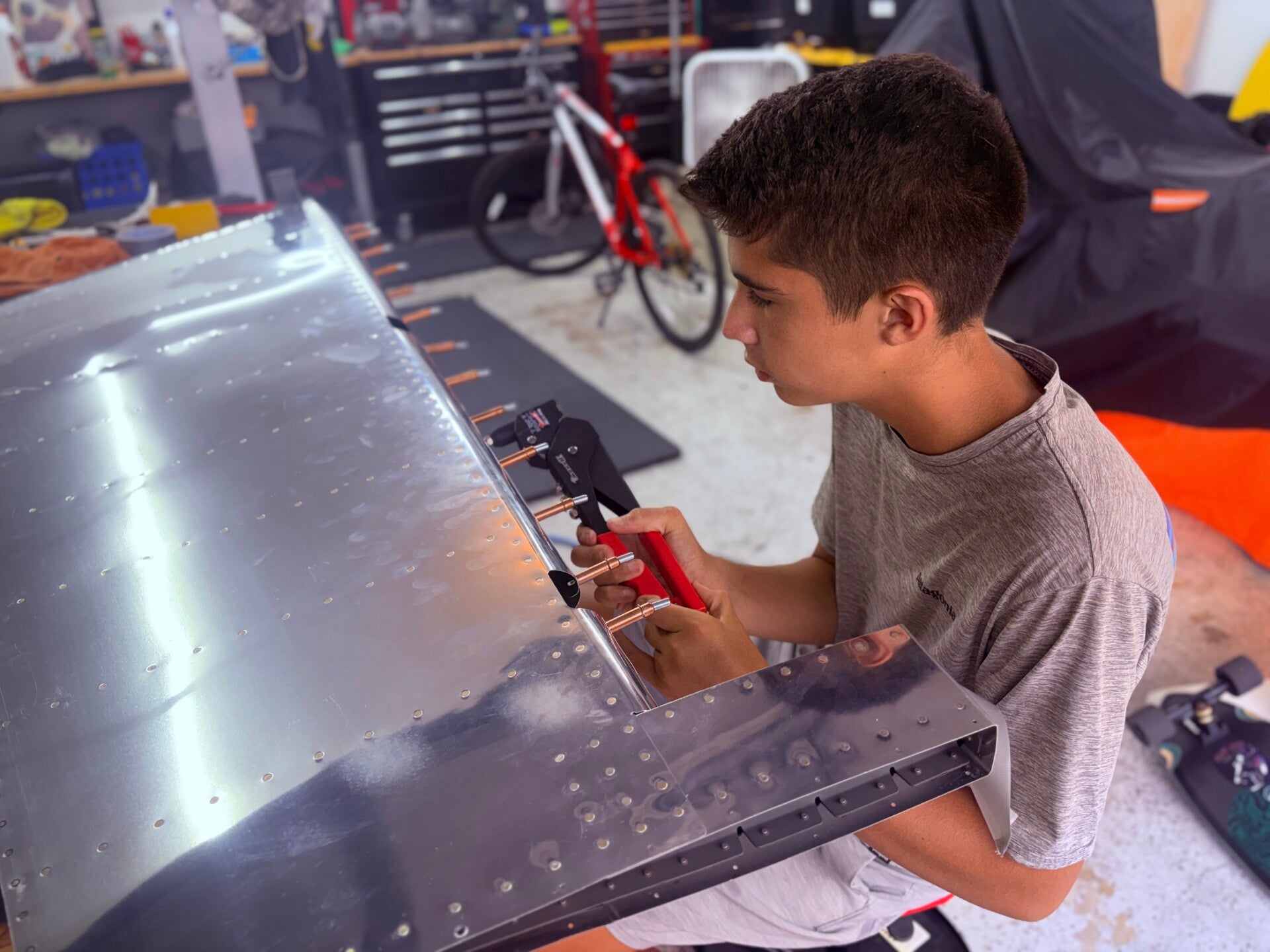
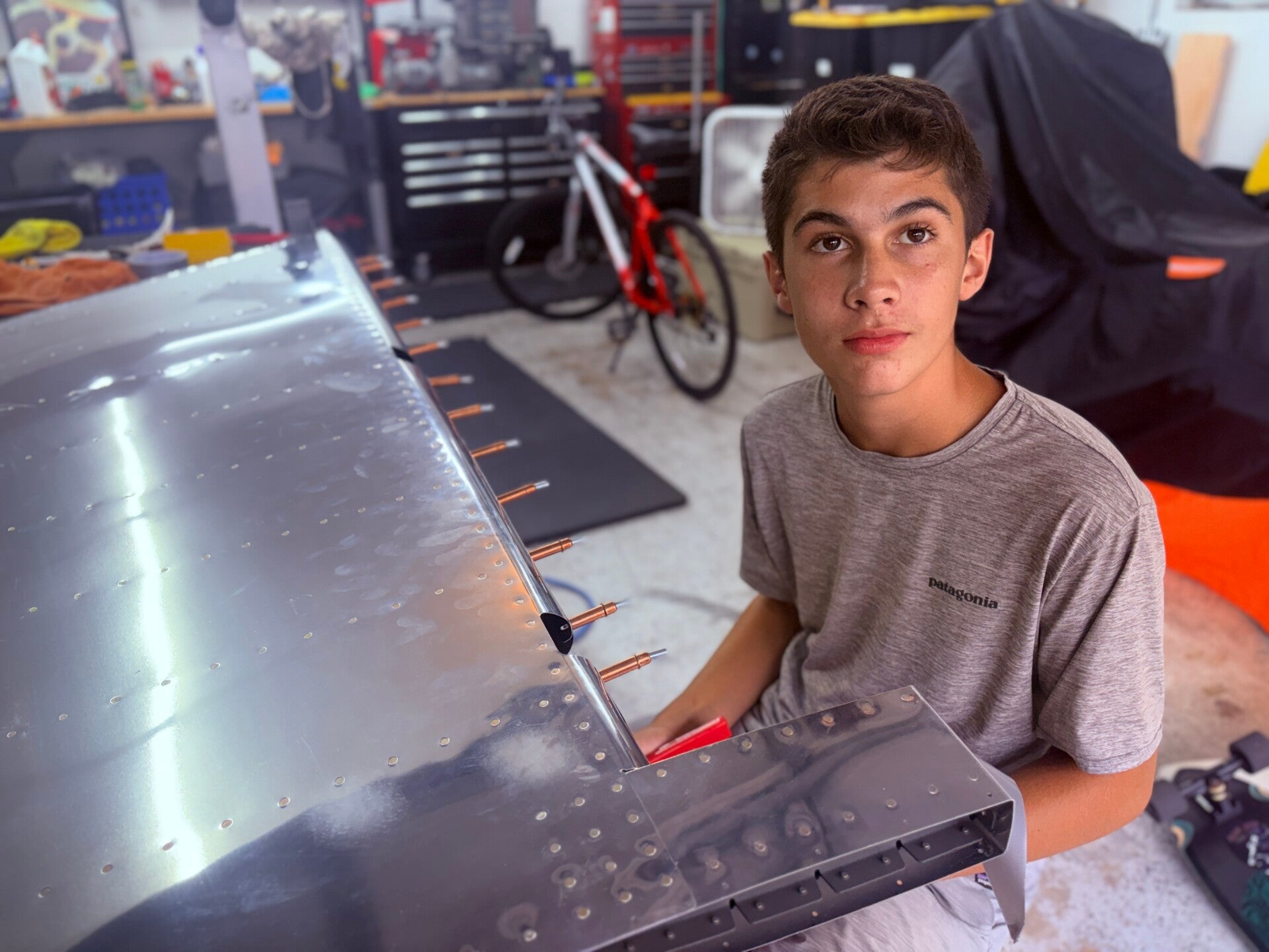
Gunnar also joined in helped a number of times but I only captured a few photos of his handy work on the leading edge.
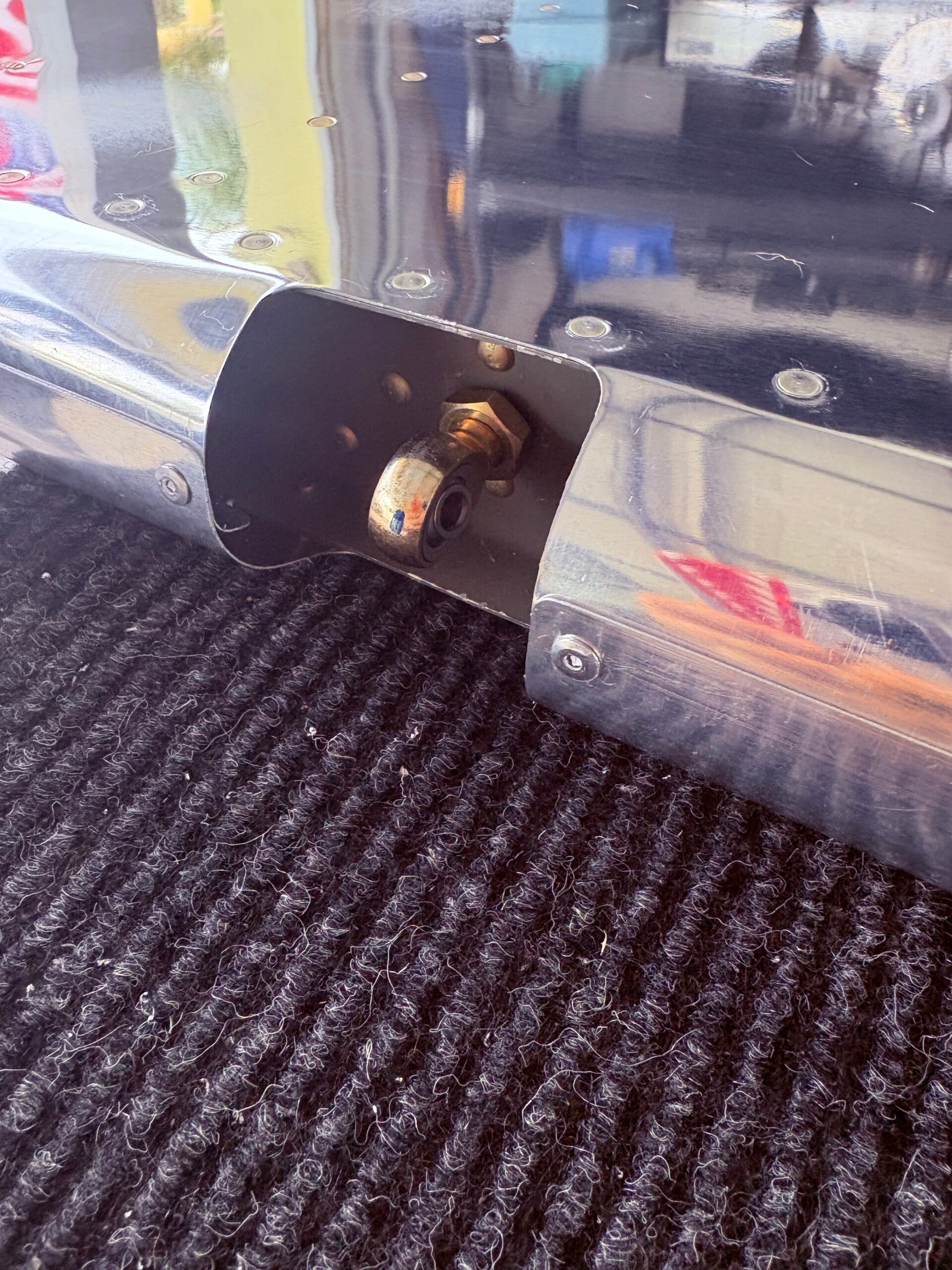
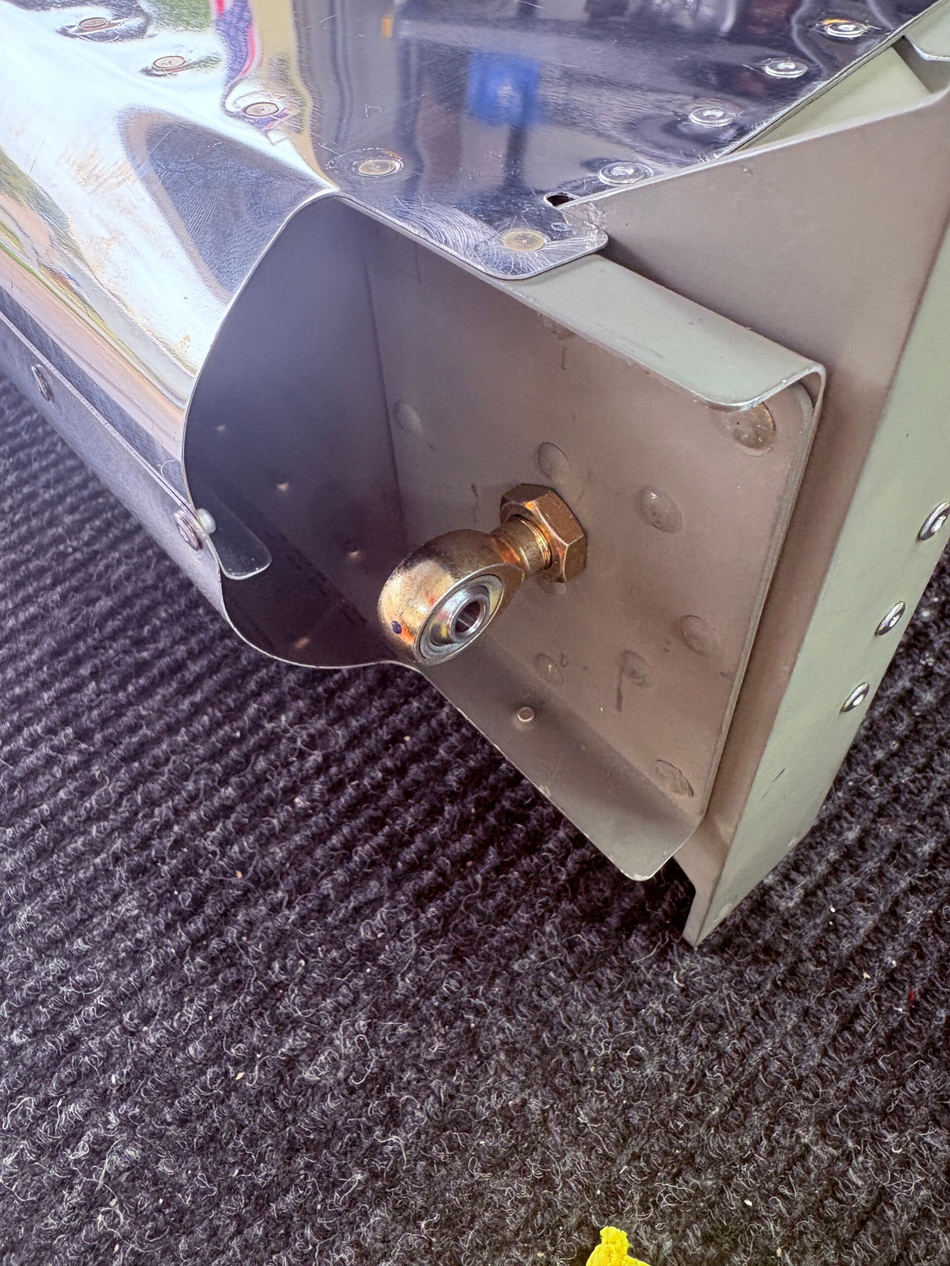
Elevators - ACTIVE
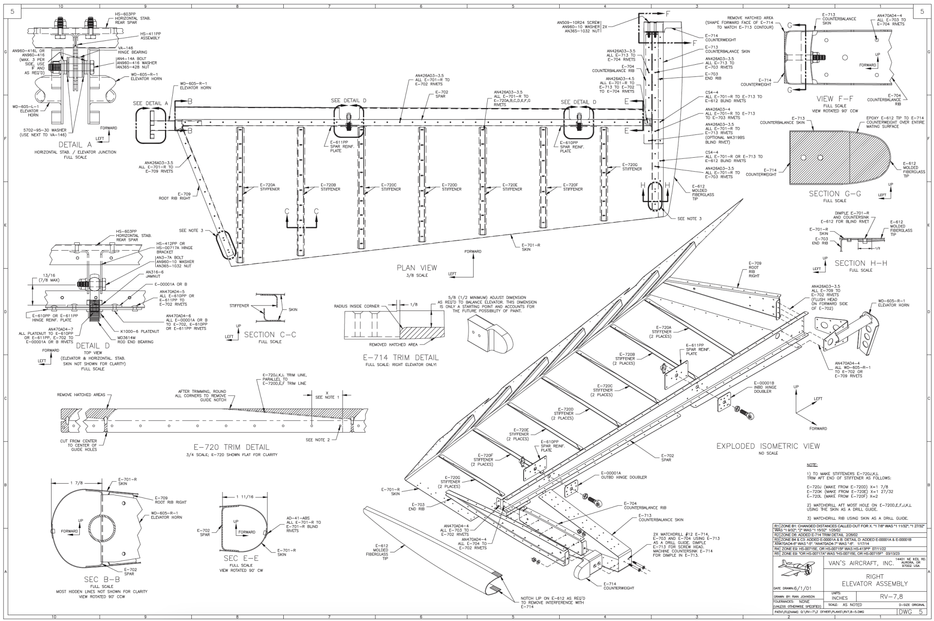
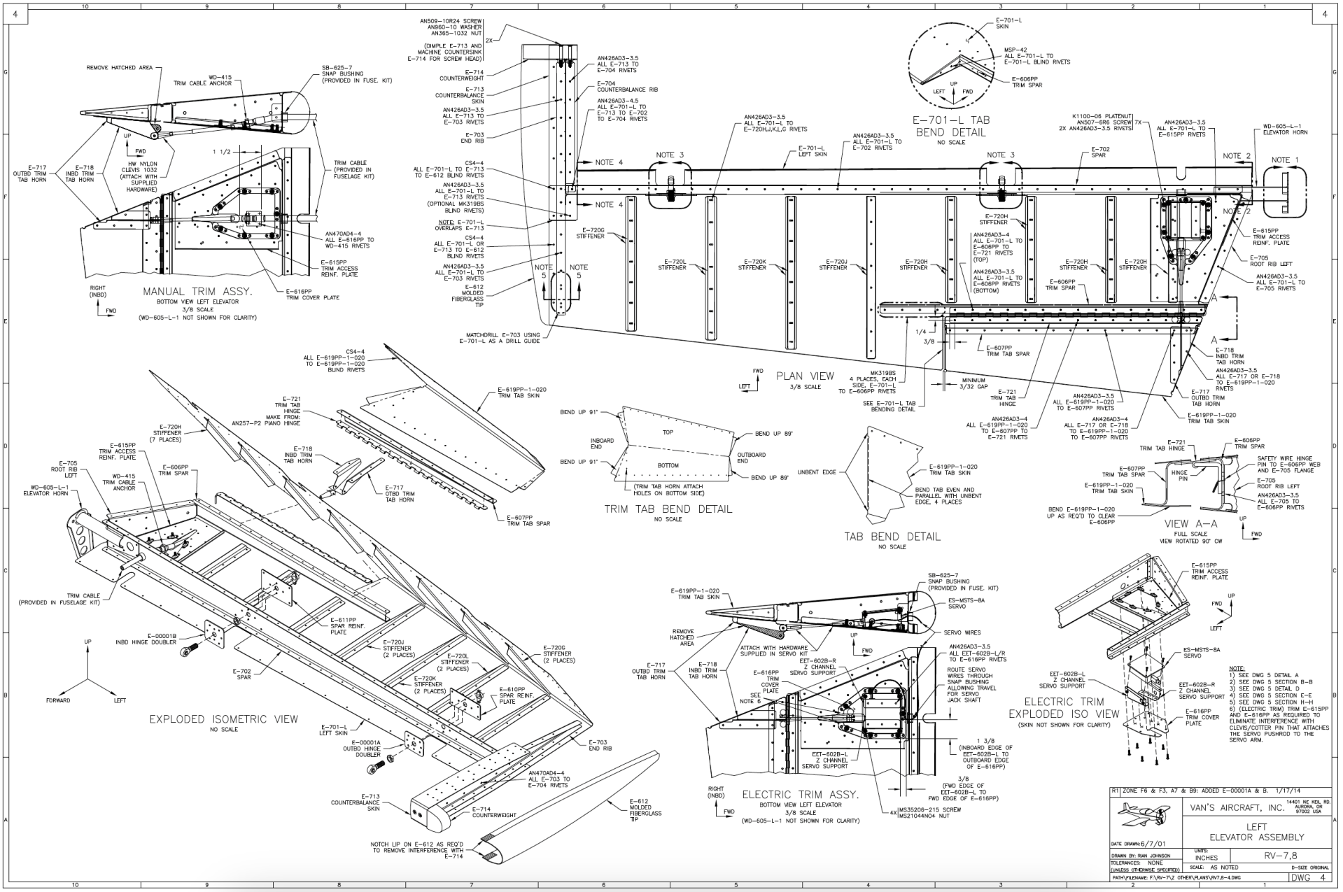
5/14/2026 (1 hours)
Manual Section 6-8
Steps 1-4
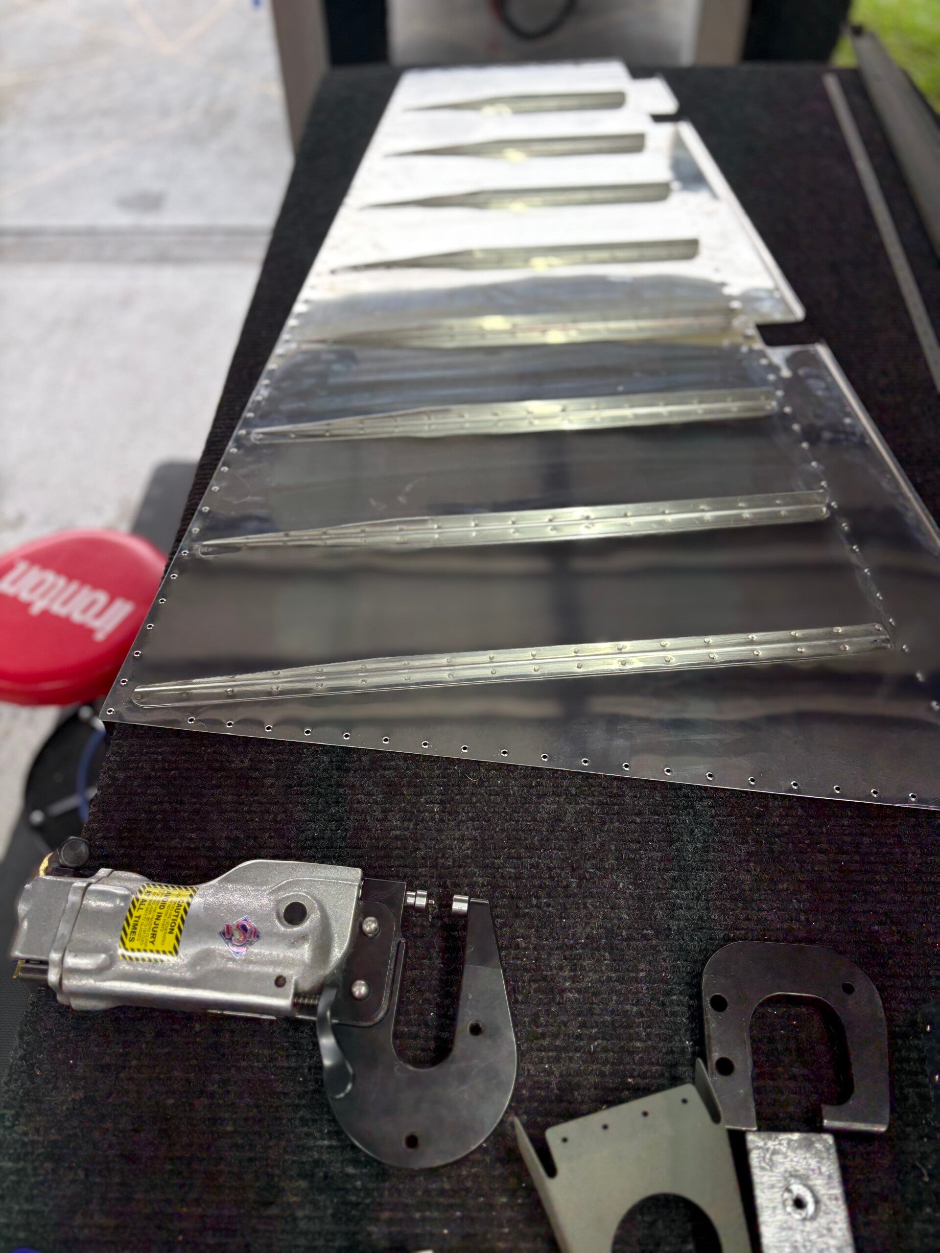
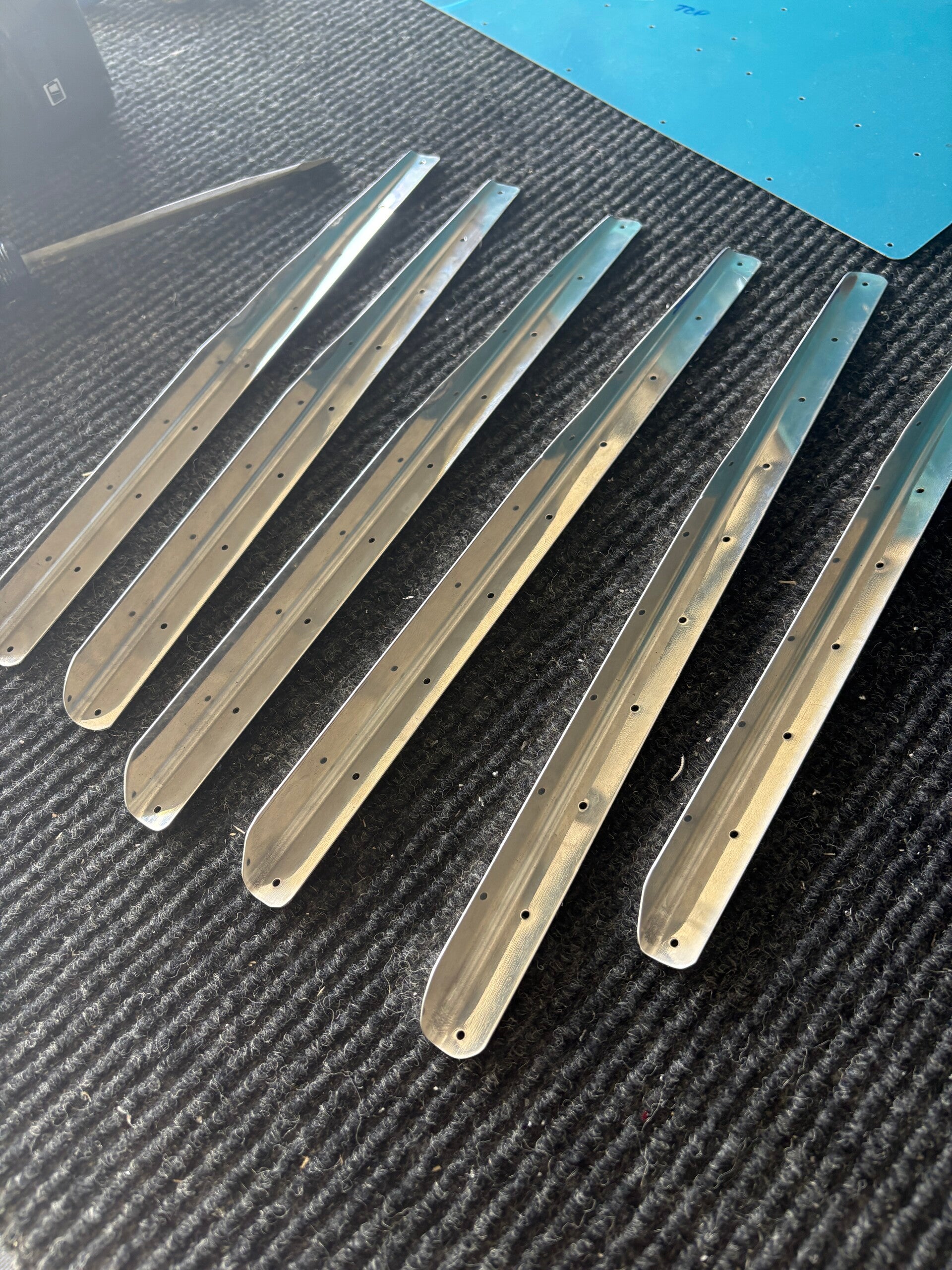
Since all other areas are on hold due to parts, I decided to start on the elevators. First step is to fabricate the stiffys. I did so for E-720A-C.
5/20/2026 (1 hours)
Manual Section 6-8
Steps 1-4
Fabricated the remaining stiffys for the right elevator. Clecoed to skin.
5/23/2026 (3.5 hours)
Manual Section 6-8
Steps 1-4
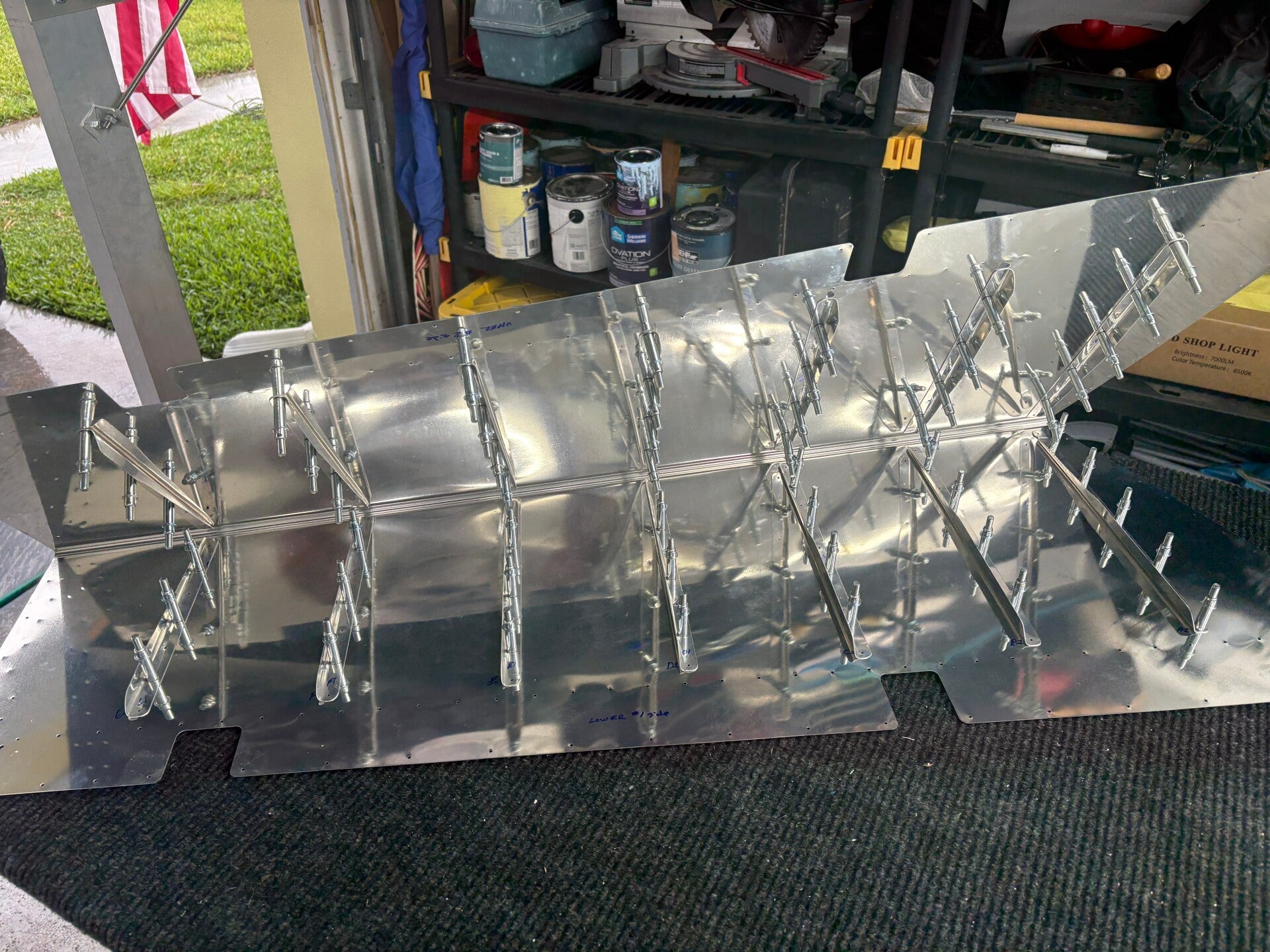
Fabricated the remaining stiffys for the left elevator. Clecoed to skin. Match drilled both left and right elevator stiffys and E-616P to the elevator skins. Deburred all stiffeners and E-616
5/26/2026 (1.0 hours)
Manual Section 6-8
Step 4
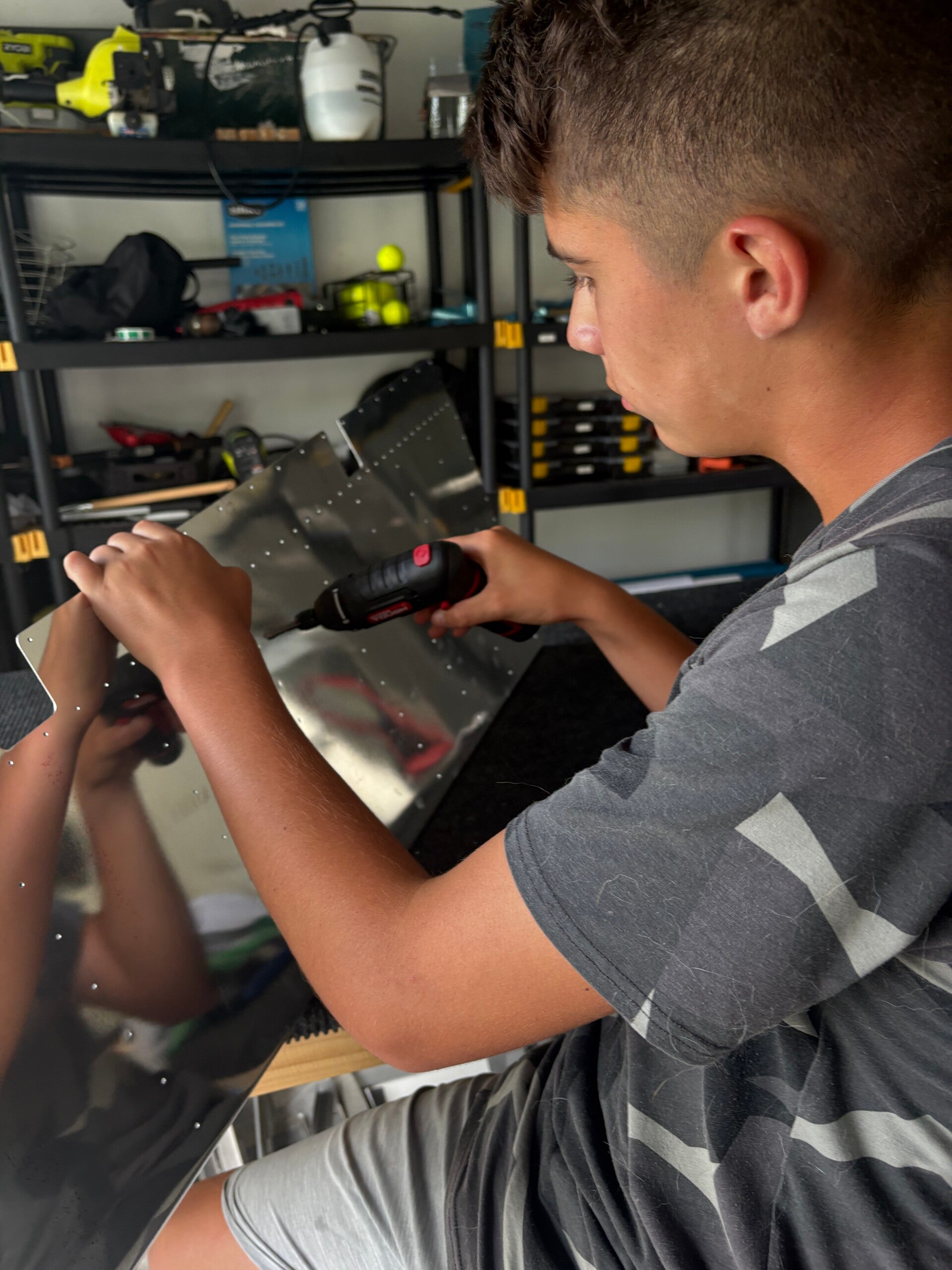
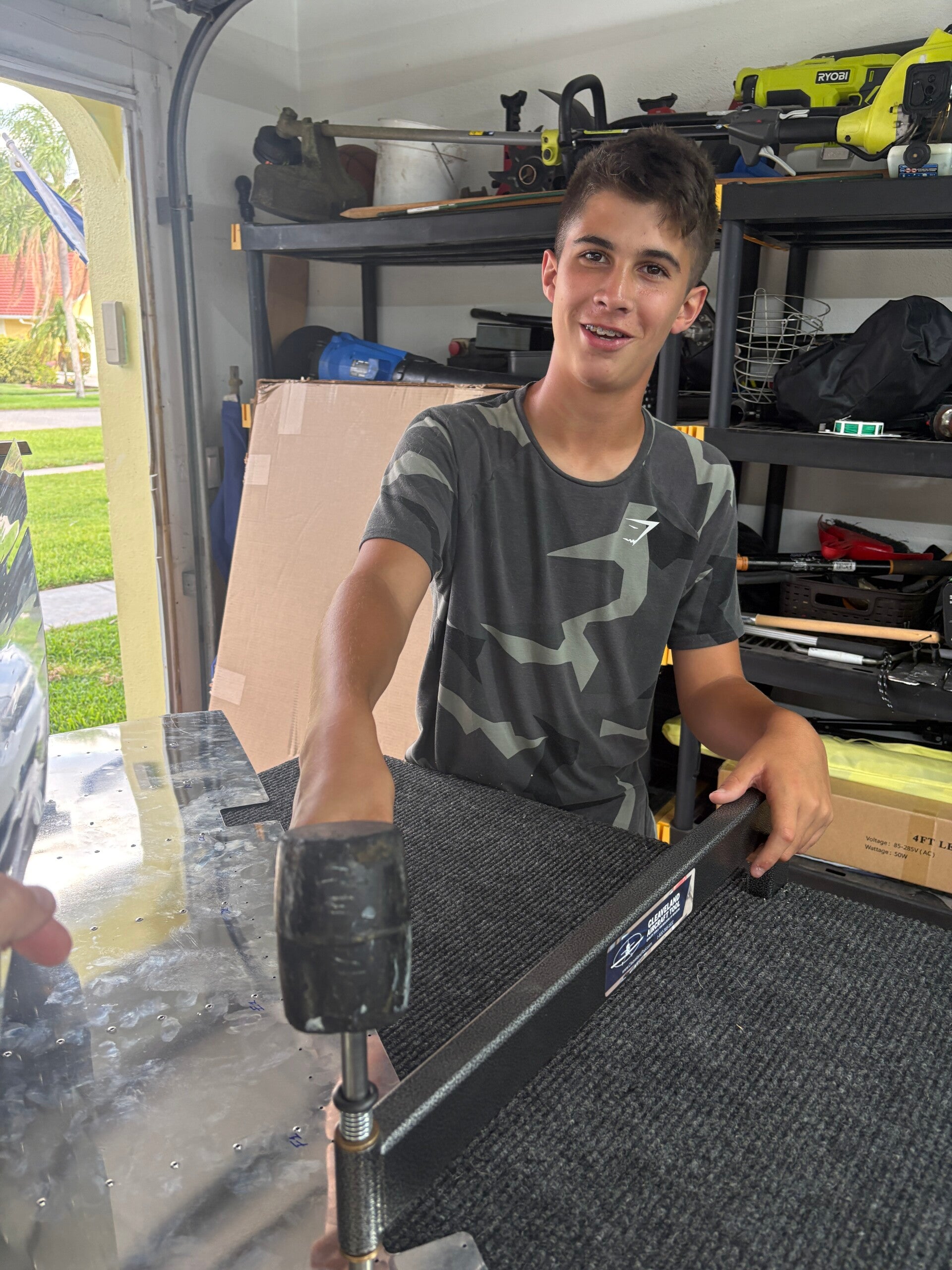
Gunnar and I deburred both elevator skins. Dimpled one elevator skin.
5/27/2026 (1.0 hours)
Manual Section 6-8
Step 4
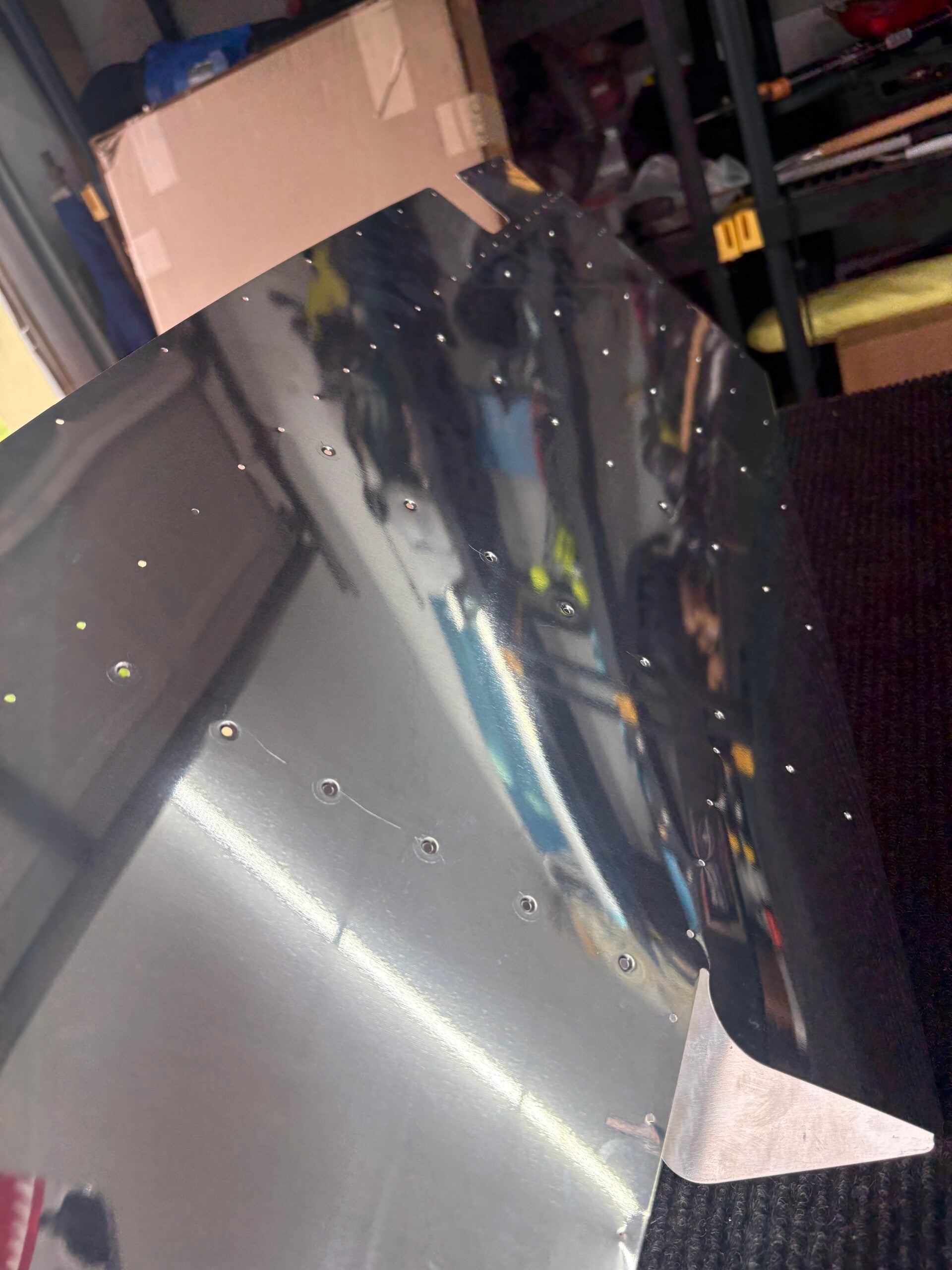
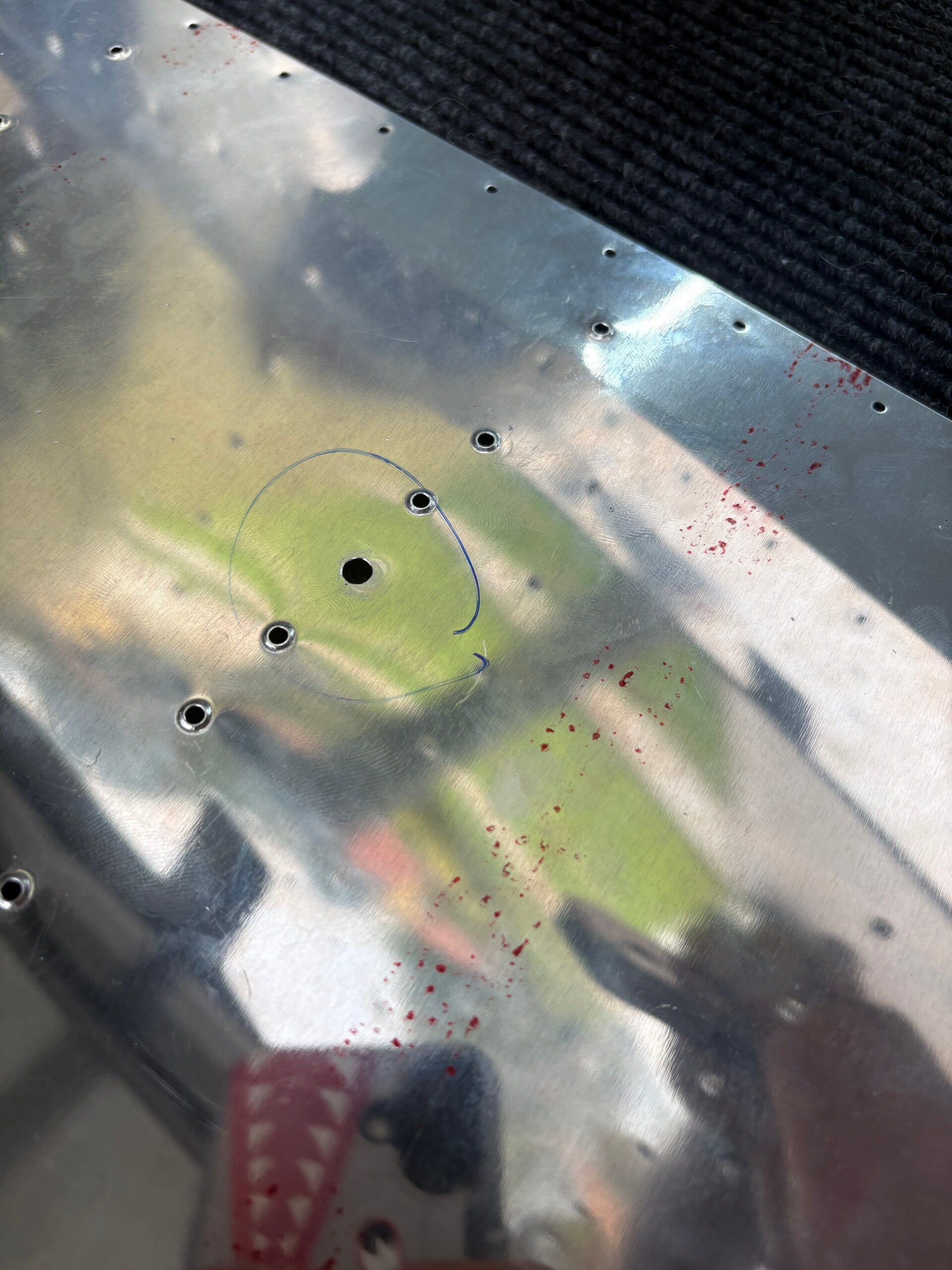
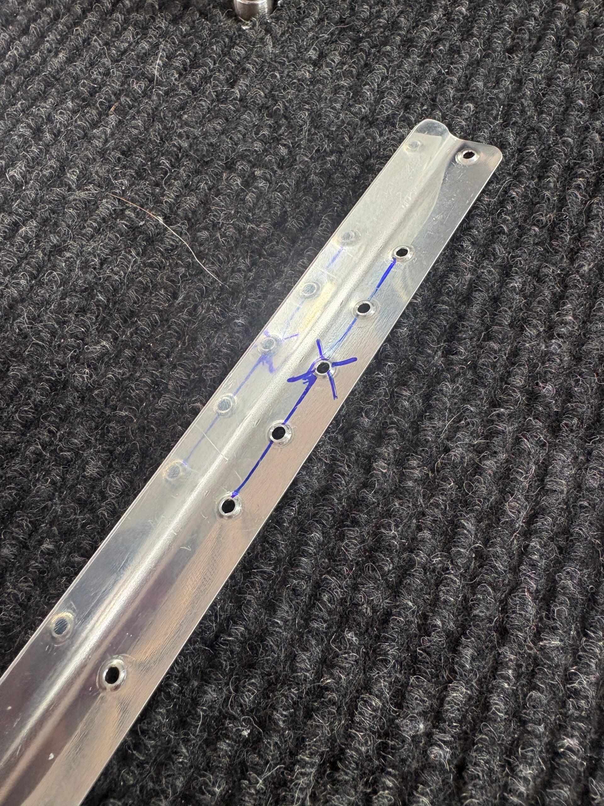
Gunnar and I dimpled the left elevator. We made a mistake with the c-frame dimpler and missed a hole to the side. So I drilled two holes on either side halfway in between and then dimpled. Flattened out and drilled out the oops hole. Then went on to dimple all stiffeners.
5/28/2026 (0.5 hours)
Manual Section 6-8
Step 4
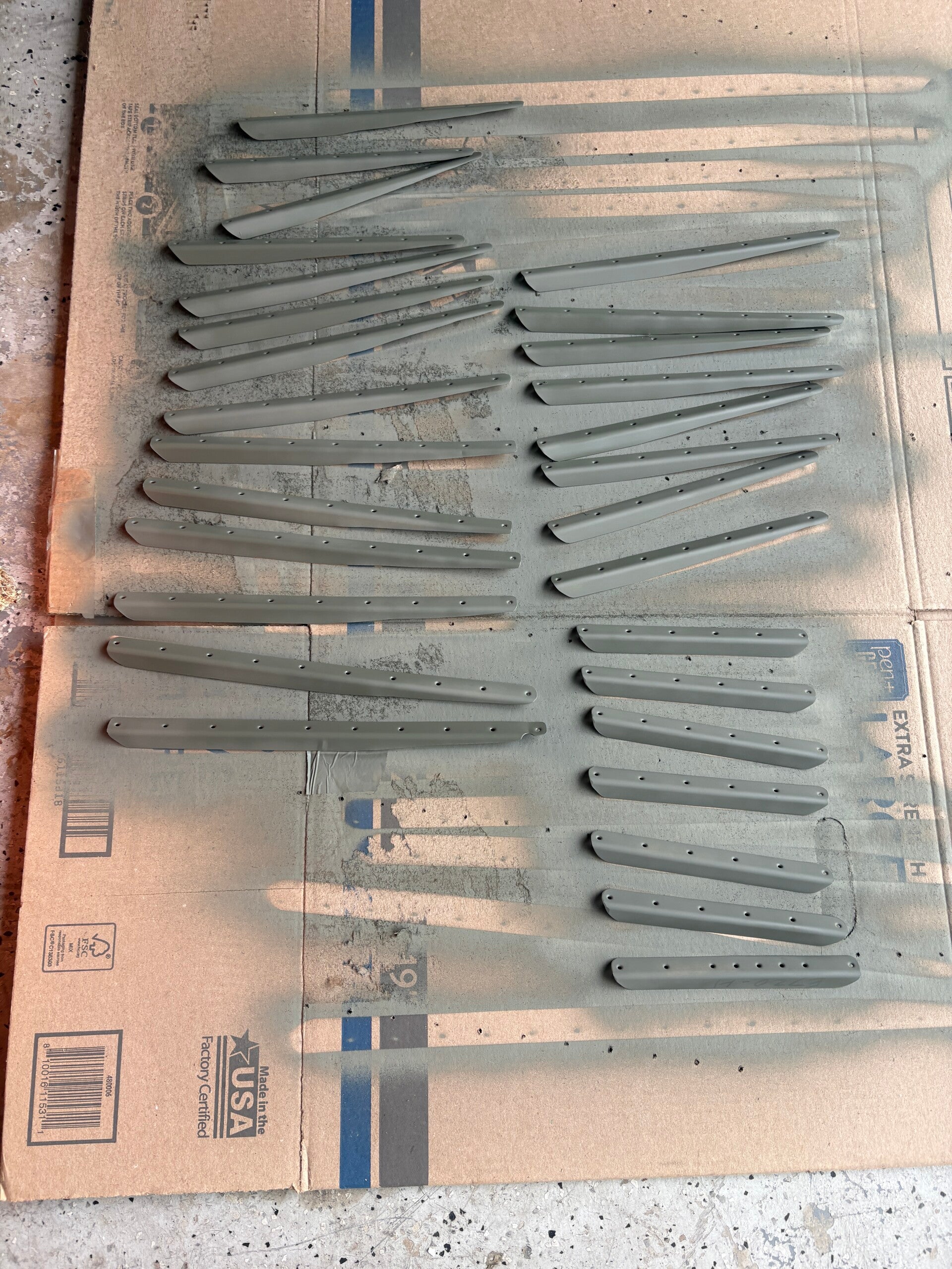
Quick night - just primed the stiffeners.
6/15/2026 (2 hours)
Manual Section 6-8
Step 4-6
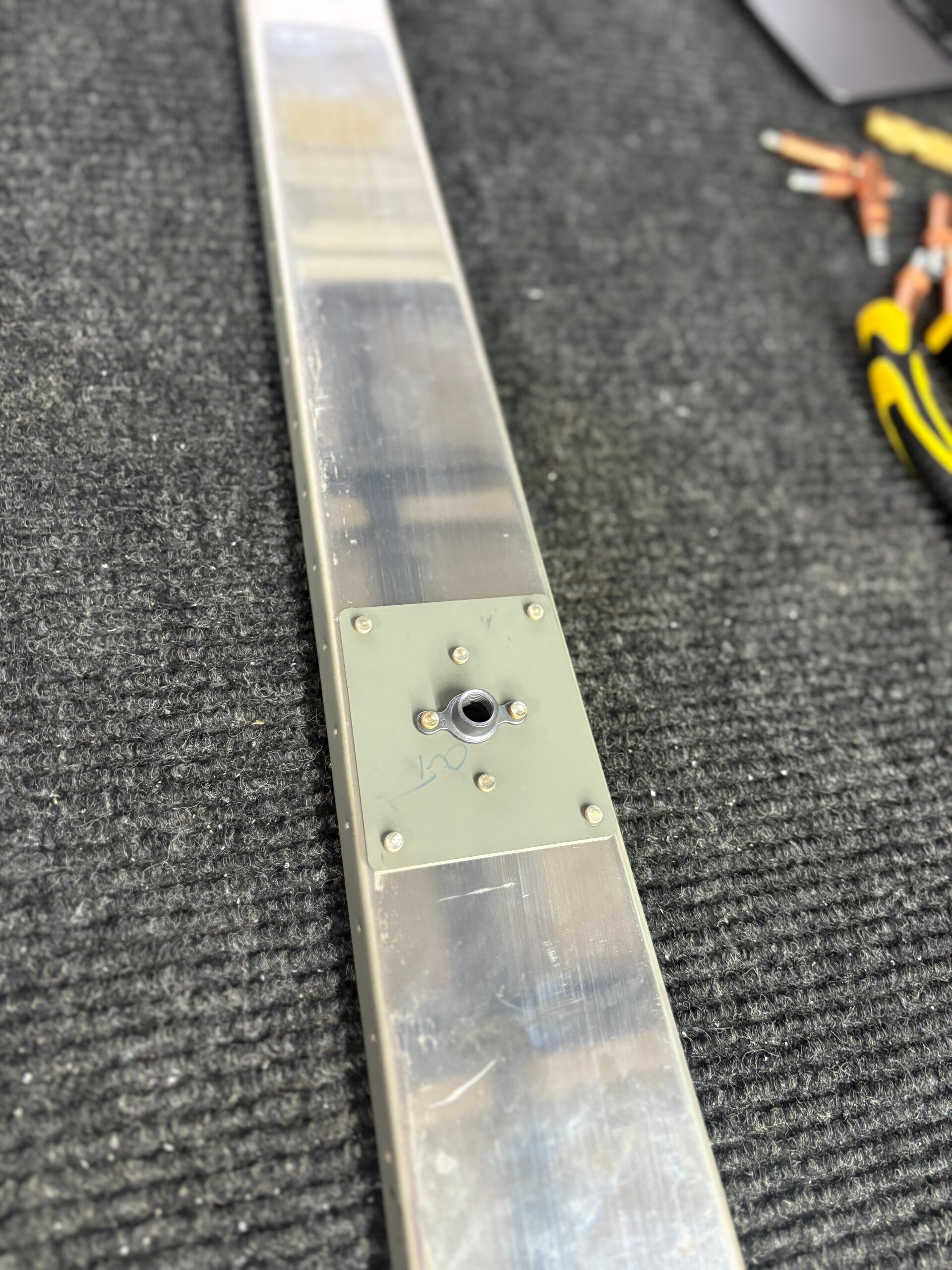
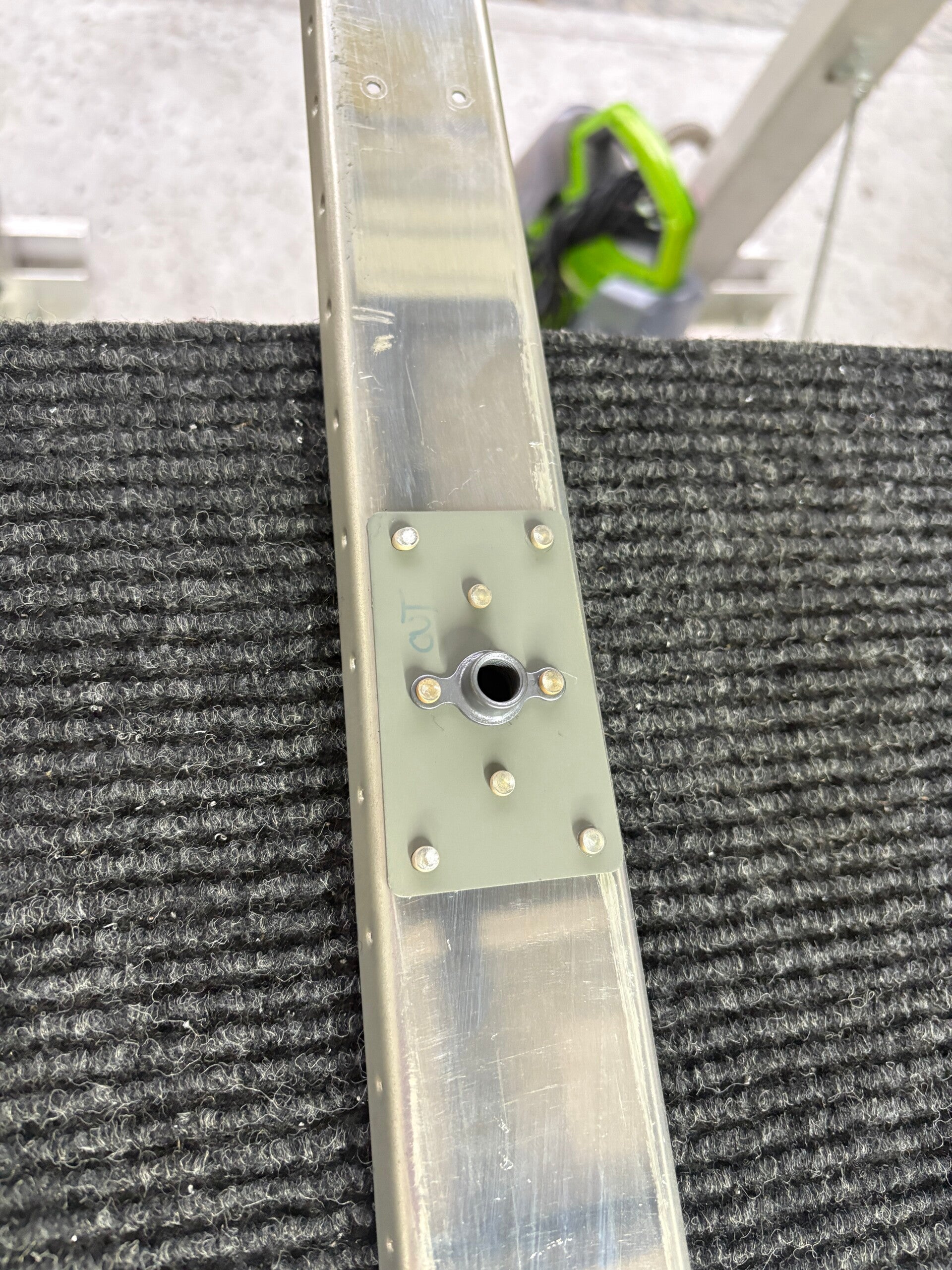
Match drilled the E-615PP to the the left elevator. Dimpled, deburred, primed and then riveted the platenuts to it. Also, riveted all stiffeners as well as the 615 to the skins. Started on the rudder left skin... see that section for more details.
6/15/2026 (6 hours)
Manual Section 6-8
Step 1-13
PREPARING THE RIGHT ELEVATOR
- The E-00001A & B hinge doublers were separated. The top and bottom edges of the E-00001A outboard hinge doubler were filed and radiused to nest against the spar radii.
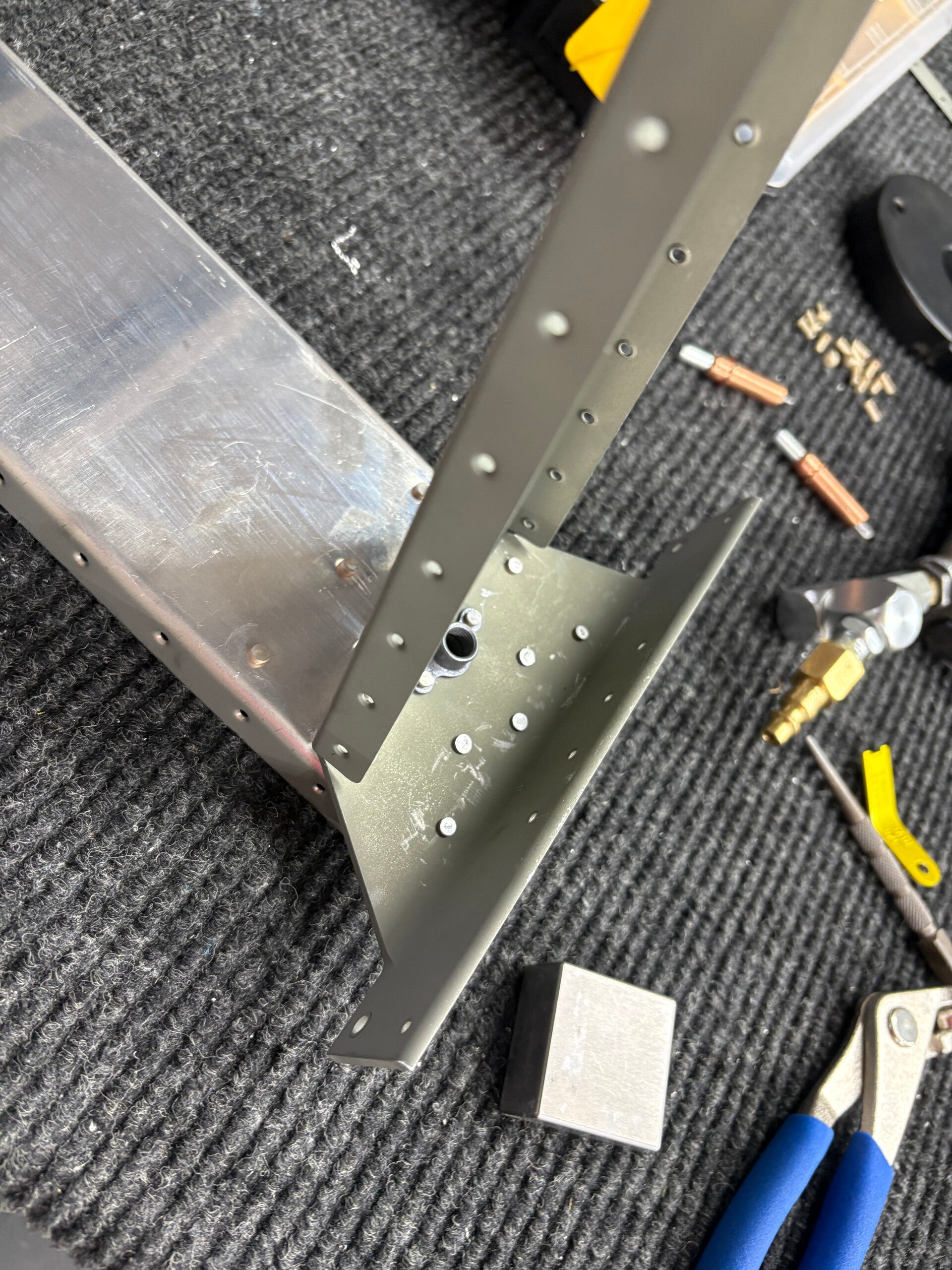
- The E-610PP and E-611PP reinforcement plates, E-00001A & B hinge doublers, and corresponding platenuts were clecoed and drilled to the E-702 spar.
- The E-703 end ribs and E-704 counterbalance ribs were prepared according to “Edge Finishing” and “Fluting,” Section 5.2 & 5.13.
- The E-703 end rib was clecoed and drilled to the E-704 counterbalance rib, then clecoed and drilled to the E-702. The ribs were then removed from the spar.
- The E-714 counterweight was positioned on the forward ends of the E-703 and E-704.
- The E-713 counterbalance skin was clecoed to the E-703 and E-704 over the E-714. The step on the forward face of E-714 was positioned against the outboard edge of E-713.
- The two holes in the forward face of E-713 were used as guides to drill #12 holes for the screws securing E-714. Drilling lubricant was used when drilling the lead E-714s.
- E-713 was unclecoed, E-714 was removed and set aside, and E-713 was re-clecoed to E-703 and E-704.
- The E-704 and E-713 subassembly was clecoed to E-702.
- The E-610PP and E-611PP reinforcement plates, E-00001A & B hinge doublers, and corresponding platenuts were clecoed and drilled to the E-702 spar.
- The E-709 root rib right was clecoed to E-702 and final drilled #40.
- E-701-R was clecoed to the understructure, with E-701-R positioned on top of E-713.
- The clecos connecting E-709 to E-702 were removed. The WD-605-1-R elevator horn was then clecoed and drilled to E-702 and E-709.